Core-to-Core Paging
Core-to-Core paging allows you to send pages to paging zones that exist on another Core. A Core can be the source of the pages, and/or the destination of the pages.
In order to use Core-to-Core Paging, the Cores must be able to discover each other and if you are using the Type Q-LAN, both Cores' clock Domain must be the same.
Core-to-Core Paging uses a TCP/IP control connection on port 1710. In a restricted network environment this port must be allowed through.
- For each Core-to-Core paging instance, there must be a Source Core, and a Destination Core.
- The Source Core requires a Remote Destination (where the pages are to be sent) with a unique Name.
- The Destination Core requires a Remote Source (where the pages are coming from) with the same Name as the Remote Destination. If the Name is not the same, the Communication Status for both the Remote Source and Remote Destination is red with the message "Fault - Not connected".
- The Type and Channel Count must match exactly.
- For the destination Core, the Q-SYS Administrator > Users > Guest > External Control Protocol parameter must be set to "Yes". Otherwise, the Remote Source tab Communication Status will show "Fault - Not connected".
Once the Remote Source and Remote Destination are added, and have the same name, communication between the two is possible.
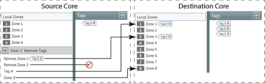
Once you have the Remote Destination and Remote Source set up, you need to add "remote" zones in the Source Core that will map to the Local Zones in the Destination Core.
In the Q-SYS Administrator on the Source Core, each Remote Destination added has a Remote Tags group. The Name of the Remote Tags group is the same as the Remote Destination. By default, the Tag groups have no zones. You can add as many zones (click the "+" sign) as the Remote Destination Core has. If you add more than the Remote Destination Core, the excess will be ignored. As you add zones, the default name is "Remote Zone n". You must rename the zones to match either the zone names in the Destination Core or a Tag defined in the Destination Core.
Tags
You can use Tags in the same way they are used for standard paging. If you name the Remote Zones with Tag names, you do not have to create Tags in the Source Core, only the Destination Core.
Commands
Create the Commands you will use to initiate the pages. You can specify the zones for a command, or use Tags.
The PA Router supports direct paging to remote zones and enables you to configure Remote Zone Groups within the Virtual Page Station (software based, touchscreen interface, customizable via Q-SYS Designer) and PS-TSCG3 Mic / Control components (physical paging station with mic and touchscreen). Each group corresponds to a Remote Destination Tag defined in Q-SYS Administrator. These tags allow a single button press to trigger paging across one or more remote zones, without relying on a traditional Zone Tag.
Note: Remote Destination Tags are independent of Zone Tags. Zone Tags continue to maintain their functionality and can be used alongside Remote Destination Tags.
Note: Traditional Zone Tags are used to group local PA Zones within a single Q-SYS Core. These Zone Tags simplify paging by allowing commands to target multiple zones using a shared tag. However, Remote Destination Tags are used for paging across multiple Q-SYS Cores. These tags are configured in Q-SYS Administrator and linked to Remote Destinations in the PA Router. Each Remote Destination Tag can represent a group of zones on a remote Core, enabling cross-core paging from a single-button press.
Requirements
-
The PA Router must have a non-zero value set for the Remote Destination Count property.
-
Remote Destination Tags must be configured in Q-SYS Administrator.
-
The Virtual Page Station or PS-TSCG3 Mic/Control component must have the Remote Zone Group Count property set to the desired number of button groups.
Configuration
1. In Q-SYS Designer:
-
Select the PA Router component.
-
Set the Remote Destination Count property to the number of remote destinations you plan to use.
-
In the Virtual Page Station or PS-TSCG3 Mic / Control component, set the Remote Zone Group Count property to match the number of Remote Tags you want to expose as buttons.
2. In Q-SYS Administrator:
-
Navigate to the Remote Destinations section.
-
Define Remote Destination Tags and assign them to the appropriate zones.
3. At Runtime:
-
Each Remote Zone Group Countappears as a button in the user interface.
-
The LED's beside the remote zone buttons will light up only when the respective remote zones are active with a paging command.
-
Pressing a button, triggers paging to the associated Remote Destination Tag.
Use Case
A hotel concierge desk uses a Virtual Page Station (software, touchscreen interface) or PS-TSCG3 Mic/Control (physical paging station with mic and touchscreen) to page different service zones across the property including—guest villas, spa areas, dining areas, and emergency response zones—all located on separate Q-SYS Cores.
1. In Q-SYS Designer:
-
Set the Remote Zone Group Count property to 4 in the Virtual Page Station component.
-
Ensure the PA Router has a Remote Destination Count of 4.
2. In Q-SYS Administrator:
-
Create four Remote Destination Tags:
-
Villas
-
Spa & Wellness
-
Dining & Lounge
-
Emergency Response
-
-
Assign the appropriate zones to each tag, even if they reside on different Cores.
3. In UCI Designer:
-
Customize the Virtual Page Station interface to display four buttons:
-
"Page Villas"
-
"Page Spas"
-
"Page Dining & Lounge"
-
"Emergency Alert"
-
-
Wire each button to the corresponding Remote Zone Group control pin.
4. At Runtime:
-
The concierge can press "Page Spa" to notify staff in all spa zones across the resort.
-
In case of emergency, pressing "Emergency Alert" instantly pages all designated safety zones across multiple locations.
Remote Destination and Remote Source
These Properties have to be the same for both Cores with the exception of the Q-LAN Verbose Property.
Name
The Name on the source must be identical to the name on the destination, and if you have more than one source/destination pair, each pair must have unique names.
By default, the source = Remote Destination 1, the destination = Remote Source 1. You must change one or both names to match.
For each Remote Destination you set up, a tab is placed across the top of the PA Router Control Panel.
Type
Select Q-LAN to communicate from one Core to another over the Q-LAN network using the number of Q-LAN streams equal to the Channel Count. Both Cores must be set to Q-LAN.
Select Direct to supply the audio to the remote Core via AES, WAN transmitter/receiver, or analog. Selecting Direct adds an output audio pin to the PA Router, giving you the responsibility of getting the audio to the other Core. Both Cores must be set to Direct.
Channel Count
The number of Q-LAN channels. Allows for multiple pages at one time, providing they do not require the same zones on the same Core.
Q-LAN Redundant
Adds LAN-B for redundancy.
Available only when Type is set to Q-LAN.
Q-LAN Verbose
Adds the Details field for the Q-LAN stream.
Available only when Type is set to Q-LAN.
Note: In most cases, you do not need to change the values of any controls in the Remote Destination Tabs. Use the controls in the Destination Core's PA Router control panel.
Remote Destination Tab
For each Remote Destination added in the PA Router Properties, one Remote Destination tab is added to the PA Router Control Panel. You can have up to 16 Remote Destinations.
Zone
Within each Remote Destination tab on the Source Core, one Zone is used for each Channel (Channel Count in Properties). When pages are made to the Remote Destination, Channels are used round-robin. You can only have as many Simultaneous pages going to the Remote Destination as there are Channels.
The Remote Destination zones are numbered starting with the first number after the local paging zone count.
Mute
Mutes all signals to the Zone. One Mute button for each Zone.
Gain (dB)
Sets the gain for all signals to the Zone.
You can enter the value using your keyboard, or change it by selecting the field and dragging the mouse.
Squelch Priority
Allows you to silence pages and messages at and below the Priority level selected.
You can create a Control Command and Schedule it to change the Squelch Priority to prevent pages and messages from being played in certain zones at certain times.
Buffer
Displays the amount of PA Router audio RAM in use.
Communication Status
Displays the connection status between the Remote Source and Remote Destination.
Controls when Type Property is set to Q-LAN.
Channel Count
The number of audio channels available for a Core-to-Core Paging instance. Each channel uses one Q-LAN Stream. The Channel Count must be the same on both Destination and Source Cores.
Peak Output Level (dBFS)
Measures the output Digital Signal level.
Invert
Inverts the audio signal.
Mute
Mutes the digital audio signal.
Gain
Controls the gain of the digital audio signal prior to the D/A converter.
Q-LAN Transmitter Status
Component status is conveyed with the Status LED and Status box, which uses both color and text to indicate the current condition:
- OK: The device is functioning normally.
- Initializing: The device is in the process of a firmware, patch, or configuration update, or the design is starting.
- Compromised: The device is functioning, but a non-fatal problem exists. Refer to the Status box for details.
- Missing: The device cannot be discovered.
- Fault: The device is malfunctioning or is not properly configured. Refer to the Status box for details.
- Unknown: This status appears during a Core reboot (for example, during a firmware update), or when a design is being uploaded to the Core and before it has started running.
- Not Present: If applicable to the device, this status appears when the device is not connected to the network and its Is Required component property is set to 'No'. This status also appears if the device component's Dynamically Paired property is set to 'Yes', pairing has not been assigned in Core Manager, and the device component's Is Required property is set to 'Yes'. See Dynamic Pairing.
Tx OK
LED indicating the status of the Transmitter network link for both LAN A and LAN B (If network redundant).
Details
Available only when Verbose is set to Yes in the Remote Destination Properties.
Text indicating the Details of the status of the Transmitter. The information in this field is updated regularly and is cumulative. The following information is displayed as running totals.
Reset Details
Available only when Verbose is set to Yes in the Remote Destination Properties.
This button resets the networking details to zero, at which point the details start accumulating information again.
Squelch
LED indicating that the associated PA Zone is being squelched.
Active
LED indicating that the PA Zone associated with the LED is Active (illuminated) or not.
Source
A number indicating the PA Router Input Pin to which the source of the page is connected.
Priority
Text field giving the Priority of the current event. One of the Priorities set in the PA Global Settings in the Administrator.
Cancel All
Cancels all executing and queued commands.
Cancel Queued
Cancels all queued commands.
Mute
Mutes the Page output for the associated PA Zone.
Gain (dB)
Sets the gain for the Page signals to the Zone.
You can enter the value using your keyboard, or change it by selecting the field and dragging the mouse.
Mute
Mutes the Message input. One Mute button for each PA Zone.
Gain
Controls the Gain of the Message. One Gain control for each PA Zone. This Gain is in addition to the Gain set in the Output section of the associated Zone.
You can enter the value using your keyboard, or change it by selecting the field and dragging the mouse.
Message
Text field displaying the name of the Message file currently playing.
Mute (Zone)
Mutes only the BGM signal to the PA Zone. One Mute button for each Zone.
Gain (dB)
Adjusts only the BGM Gain for a single PA Zone. One Gain control for each PA Zone. This Gain is in addition to the Gain set in the Output section of the associated Zone.
You can enter the value using your keyboard, or change it by selecting the field and dragging the mouse.
Select
Displays the number of the BGM Input button you have selected for the associated Zone. In addition, you can select the Select field, and type the number corresponding to the BGM Input you wish to select.
BGM input buttons 0 - n
Radio button for each BGM Input defined in the BGM Input Count in the Properties. The buttons are numbered 1 - n, and the number of the one you select displays in the Select field. A set of buttons (1 - n) is available for each Zone.
When you select a button, the audio source connected to that BGM Input is routed to the associated Zone.
BGM Input Gain (dB)
Adjusts the BGM Input Gain for all PA Zones associated with that BGM Input. One Gain control for each BGM Input.
BGM Ducker Attack (Seconds)
The Attack is the time it takes the BGM to fall to 63% of the Depth level when the a Page or Message is played.
Use this control to provide a smooth transition from the BGM audio to the Page or Message audio.
BGM Ducker Depth (dB)
The Depth sets the amount of gain applied to the BGM Input channels when the BGM Ducker is activated. The Page or Message is mixed with the BGM, so the Depth setting controls how much of the BGM is heard in the output. Setting the Depth to 60 dB of attenuation essentially mutes all BGM channels used by the Page or Message.
BGM Ducker Release (Seconds)
The Release Time is the time it takes the BGM channel outputs to return to 63% of their normal level when the BGM Ducker is deactivated - the Page or Message ends.
Use this control to provide a smooth transition from the Page or Message audio back to the BGM channel audio.
Remote Source Tab
For every Remote Destination set up in the source Core, there must be one Remote Source set up in the Destination Core.
Communication Status
Displays the connection status between the Remote Source and Remote Destination.
Controls when Type Property is set to Q-LAN.
Peak Input Level (dBFS)
Measures the Input Digital Signal level.
Invert
Inverts the audio signal.
Mute
Mutes the audio signal.
Gain
Controls the gain of the digital audio signal prior to the D/A converter.
Q-LAN Transmitter Status
Component status is conveyed with the Status LED and Status box, which uses both color and text to indicate the current condition:
- OK: The device is functioning normally.
- Initializing: The device is in the process of a firmware, patch, or configuration update, or the design is starting.
- Compromised: The device is functioning, but a non-fatal problem exists. Refer to the Status box for details.
- Missing: The device cannot be discovered.
- Fault: The device is malfunctioning or is not properly configured. Refer to the Status box for details.
- Unknown: This status appears during a Core reboot (for example, during a firmware update), or when a design is being uploaded to the Core and before it has started running.
- Not Present: If applicable to the device, this status appears when the device is not connected to the network and its Is Required component property is set to 'No'. This status also appears if the device component's Dynamically Paired property is set to 'Yes', pairing has not been assigned in Core Manager, and the device component's Is Required property is set to 'Yes'. See Dynamic Pairing.
Rx OK
LED indicating the status of the Transmitter network link for both LAN A and LAN B (If network redundant).
Details
Available only when Verbose is set to Yes in the Remote Destination Properties.
Text indicating the Details of the status of the Transmitter. The information in this field is updated regularly and is cumulative. The following information is displayed as running totals.
Reset Details
Available only when Verbose is set to Yes in the Remote Destination Properties.
This button resets the networking details to zero, at which point the details start accumulating information again.
The available Control Pins depend on settings in Properties.
|
Pin Name |
Value |
String |
Position |
Pins Available |
|---|---|---|---|---|
|
Gain |
-100 to 20 |
-100 dB to 20 dB |
0.000 to 1.00 |
Input / Output |
|
Invert |
0 1 |
normal invert |
0 1 |
Input / Output |
|
Level |
-100 to 20 |
-100 dB to 20 dB |
0.000 to 1.00 |
Output |
|
Mute |
0 1 |
unmute mute |
0 1 |
Output |
|
Pin Name |
Value |
String |
Position |
Pins Available |
|---|---|---|---|---|
|
Active |
0 1 |
false true |
0 1 |
Output |
|
BGM n Select |
0 1 |
false true |
0 1 |
Input / Output |
|
BGM Gain |
-100 to 20 |
-100 dB to 20 dB |
0.000 to 1.00 |
Input / Output |
|
BGM Mute |
0 1 |
unmuted muted |
0 1 |
Input / Output |
|
BGM Select |
1 through n |
1 through n |
0 to 1 |
Input / Output |
|
Gain |
-100 to 20 |
-100 dB to 20 dB |
0.000 to 1.00 |
Input / Output |
|
Message |
Text name of the message file currently playing |
Output |
||
|
Message Gain |
-100 to 20 |
-100 dB to 20 dB |
0.000 to 1.00 |
Input / Output |
|
Message Mute |
0 1 |
unmuted muted |
0 1 |
Input / Output |
|
Mute |
0 1 |
unmuted muted |
0 1 |
Input / Output |
|
Page Gain |
-100 to 20 |
-100 dB to 20 dB |
0.000 to 1.00 |
Input / Output |
|
Page Mute |
0 1 |
unmuted muted |
0 1 |
Input / Output |
|
Priority |
0 n |
Text names of the Priorities defined. |
0.000 to 1.00 |
Output |
|
Source |
0 n |
0 n |
0.000 to 1.00 |
Output |
|
Squelch (Squelch Priority) |
0 1 n |
Text names of the Priorities defined. |
0.000 to 1.00 |
Input / Output |
|
Squelch Active (LED) |
0 1 |
false true |
0 1 |
Output |
1. No Squelch is 0 (zero) and 1 - n are the priority levels with 1 (one) being the highest priority. |
||||
When there is at least one BGM Channel defined, the following controls are provided.
|
Pin Name |
Value |
String |
Position |
Pins Available |
|---|---|---|---|---|
|
Attack Time |
0.0 to 5 |
0 ms to 5 s |
0.000 to 1.00 |
Input / Output |
|
Depth |
0 to 60 |
0 dB to 60 dB |
0.000 to 1.00 |
Input / Output |
|
Release Time |
0.0 to 10 |
0.0 ms to 10 s |
0.000 to 1.00 |
Input / Output |
For each BGM Input the following controls are provided.
|
Pin Name |
Value |
String |
Position |
Pins Available |
|---|---|---|---|---|
|
Gain |
-100 to 20 |
-100 dB to 20 dB |
0.000 to 1.00 |
Input / Output |
|
Mute |
0 1 |
unmuted muted |
0 1 |
Input / Output |
|
Pin Name |
Value |
String |
Position |
Pins Available |
|---|---|---|---|---|
|
Buffer Used |
Text Field |
Output |
||
|
Cancel all Commands |
Trigger |
Input/Output |
||
|
Cancel Queued Commands |
Trigger |
Input/Output |
||
|
Communications Status |
Text Field |
Output | ||
|
LAN A / B Details (LAN B only when Q-LAN us redundant) |
Text Field | Output | ||
|
LAN A / B OK (Tx OK LED) (only when Q-LAN is redundant) |
0 1 |
false true |
0 1 |
Output |
| Status | ||||
Control Link: Control Signals.
Q-LAN Receiver / Q-LAN Transmitter: Unicast Audio Streams.
System Link: AV Streams & Multicast Audio Streams.
Q-LAN Bandwidth Compile Error
You cannot achieve both max stream and channels at the same time. The max stream count needs to be 256 to allow 256 single-channel streams. Configurations of 256x2 thru 256x16 all exceed line bandwidth.