IR Output (QIO-IR1x4)
The IR Output component represents an IR Output 1-4 connection on a QIO-IR1x4 device. Use the component to monitor IR activity, set the drive strength of the IR signal, and view the command code actively being sent.
Input Pins
 IR Source n
Connect this pin to the IR Driver Out pin of the IR Driver component or to the IR Input Out pin of the IR Input (QIO-IR1x4) component. You can wire multiple IR sources to the component by adjusting the IR Source Count property. See Properties.
Output Pins
Serial Port 
This pin only appears when Serial RS-232 is selected for the Data Format property. Wire this pin to a downstream Scripting Component. To learn more, see SerialPorts.
These examples demonstrate some use cases for all four IR-related components in Q-SYS Designer Software:
- IR Driver and IR Receiver, which are located within the Schematic Elements > Components > Control Components category
- IR Input and IR Output, which are located within the QIO-IR1x4's Inventory tree.
Sending IR Commands
In this example, an IR Driver sends commands for a TV device to a single TV (or perhaps multiple TVs of the same model) in the same room.

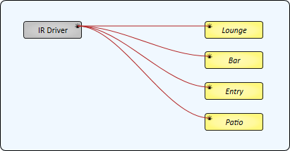
In this example, an IR Driver sends commands for a TV device to each of the four IR Outputs of the IR1x4. An emitter is placed in each room, and each room has the same model TV. This example shows a hypothetical setup for a restaurant that contains four spaces with entertainment.
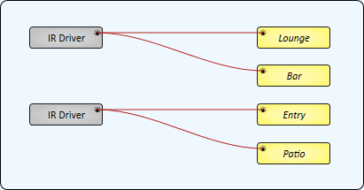
This example is similar to Example 2, except that two rooms have TVs of one model and the other two rooms use a different model. Therefore, two IR Drivers are required.
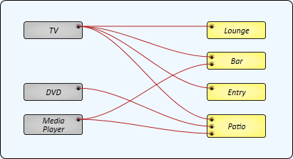
This example demonstrates how multiple IR Drivers - each for a different IR device - can be sent to multiple IR Outputs, with some IR Outputs sending IR commands from multiple sources. Each room has an IR emitter connected to an IR Output of the QIO-IR1x4.
- The Lounge and Entry only contain a TV.
- The Bar contains both a TV and a Media Player. Its IR Source Count property is set to '2'.
- The Patio has a TV, DVD player, and Media Player. Its IR Source Count property is set to '3'.
Note: For those IR Outputs sending commands from multiple sources (Bar and Patio), only a single IR command can be sent at a time.
Receiving IR Commands
In this example, the QIO-IR1x4's IR Input receives IR commands from an IR device – for example, a remote control for a TV that is not in the IR Driver's database. Each command can then be saved and labeled in the IR Receiver component.
Tip: Commands are saved locally within the IR Receiver component within the design.

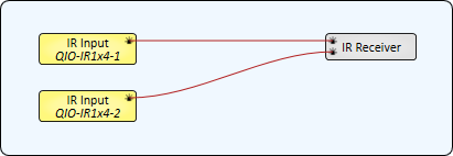
In this example, an IR Receiver can learn commands from two QIO-IR1x4 devices. The IR Receiver's IR Source Count property is set to '2'.
Similar to Example 5, an IR Receiver learns commands from a QIO-IR1x4's IR Input. However, those learned commands can then be sent to one or more IR Outputs. In this example, the IR Receiver's Enable Transmit property is set to 'Yes'.

In this example, an IR Receiver receives commands from an IR Driver. This is useful for relabeling commands from the IR Driver's database when a different description is desired.

Relaying IR Commands
In this example, a QIO-IR1x4's IR Input is wired directly to its IR Outputs. This would be useful if you have an IR receiving device in one area but you want to control IR devices in other areas that are out of view of the receiver. The QIO-IR1x4 will simply relay the received commands to its outputs.
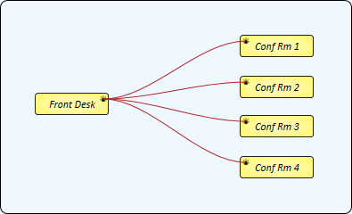
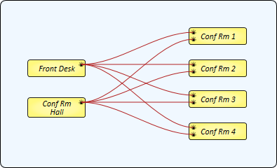
This example is the same as Example 9, except that the Conference Room devices can be controlled from two locations. "Front Desk" represents the IR Input on one QIO-IR1x4 device, while "Conf Rm Hall" is the IR Input on another QIO-IR1x4.
Tip: For additional properties that are not listed, refer to the Properties Panel help topic for more information.
Debug
When set to 'Yes', you can test IR output functionality with a Transmit Code control in the control panel. The default is 'No'.
Data Format
Select whether the IR Output communicates in IR format (default) or Serial RS-232. If Serial RS-232 is selected, a Serial Port output pin appears for connection to downstream Scripting Components. To learn more, see SerialPorts.
Note: RS-232 Mode supports TX only.
IR Source Count
Specify how many IR Source pins are available for upstream IR connections, from 1 to 50 (default is 1).
Assign component to
Select whether the IR Output is assigned to the Core (default) or an I/O Frame in your design. For I/O Frame, you must also type the Name of the device in your design.
IR Mode
Port Activity
This LED turns on whenever the IR Output port is actively sending information.
Drive Strength
Select the strength of the signal from the QIO-IR1x4 IR Output: Low (default), Medium, or High. You might need to increase the strength to overcome longer distances between the IR emitter and the receiving device.
Active Code
This is the IR code currently being transmitted from the IR Output.
Serial RS-232 Mode
Note: RS-232 Mode supports TX only.
TX Bytes
Displays a running total of the number of transmitted bytes of data.
Reset
Click to reset the TX Bytes counter to zero.
IR Emitter/Transmitter support
The QIO-IR1x4 works with a wide range of emitters/transmitters from various manufacturers. Devices from Inteset, BAFX, Herfair, and uxcell have been used successfully with QIO-IR1x4. However, these devices can vary widely with regard to pinout, operating voltage, and supported carrier frequency. Refer to the manufacturer's specification sheet to confirm compatibility.
IR Input: "Compromised - IR Rx protocol not recognized" error
This error indicates that auto detection of the IR carrier frequency has failed. You can either try sending a code again (and attempt to detect the Carrier Frequency again) or turn off the Auto Detect control and manually specify a Carrier Frequency based on the IR device specifications.
