USB Output
Use the USB Output component to see the connection status between the USB device port (USB-B or USB-C) of a supported Q-SYS Core processor or peripheral and the host USB device receiving HID signals from the USB Router component or directly from the USB Input of another Q-SYS Core processor or peripheral.
These Q-SYS devices support the ability to connect and route USB HID device signals.
| Q-SYS Core or Peripheral | USB-A Ports | USB-B Ports | USB-C Ports |
|---|---|---|---|
|
4 |
1 |
1 |
|
|
4 |
1 |
1 |
|
|
62 |
1 |
N/A |
|
|
4 |
1 |
N/A |
|
|
1 |
N/A |
1 |
|
|
2 |
N/A |
1 |
|
|
3 |
1 |
N/A |
1. The USB Input and USB Output components are not supported in Peripheral Mode (I/O Mode) for these devices.
2. On the Core 110f v2, the two front panel USB-A ports are not present. These correspond to Port 1 and Port 2 in the USB Input component and are not applicable to the Core 110f v2.
Supported HID Devices
- QSC has tested and supports the direct connection of driverless USB HID devices. These include keyboards, mice, and "smart display" touch screen interfaces (single-touch support only) connected directly to the Q-SYS hardware without a USB hub.
- QSC has not tested and does not support connection and routing of other USB devices and signals, including USB hubs, faders, joysticks, music keyboards, UVC signals (such as webcams), USB storage (flash drives, external drives), and other non-HID USB signals. Keyboard custom/special keys are not supported.
- Supported Operating Systems: Our support is limited to Windows and macOS environments.
Note: The mouse function through USB HID routing is currently not supported on ChromeOS.
USB Connections
- Connect USB HID devices to the Q-SYS Core or peripheral's USB-A and USB-C ports.
- Connect a USB host to either the USB-B or USB-C port.
Note: The USB-C port can connect to either a device or a host. However, only one host connection is supported at a time. If both the USB-C and USB-B ports are connected to hosts, the USB-B port takes priority – the USB-B port connects to a host while the USB-C port connects to a device.
In Q-SYS, you can route HID signals in addition to audio and video signals. A common application is extending a keyboard & mouse or touch screen to networked devices.
Components
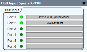
USB Input is an Inventory component for supported Q-SYS hardware. It provides a visual representation of what is connected to the USB-A ports on the Q-SYS device. The information is provided by the connected USB HID device.
For example, here is a Q-SYS Core 110f processor with a keyboard and mouse connected to two of its six USB-A ports:
USB Output is an Inventory component for supported Q-SYS hardware. It provides a visual representation of the USB-B or USB-C connector on a given device, and indicates any issues or missing connections between the Q-SYS device and the connected host. For example:

USB Router is a Schematic Elements component (available from the Control Components category) that routes input signals from one or more peripherals to one or more destination peripherals.
Note: While you can route multiple inputs to a single output, you cannot route a single input to multiple outputs.
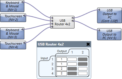
For example, here is a USB Router component configured to route USB HID signals from four NV-32-H devices:
- A keyboard and mouse (connected to NV-1) and a touch screen device (connected to NV-2) are routed to a PC connected to a Core 110f.
- A keyboard and mouse (connected to NV-3) and a touch screen device (connected to NV-4) are routed to a second PC connected to another NV-32-H (NV-5).
Use Cases and Schematic Examples
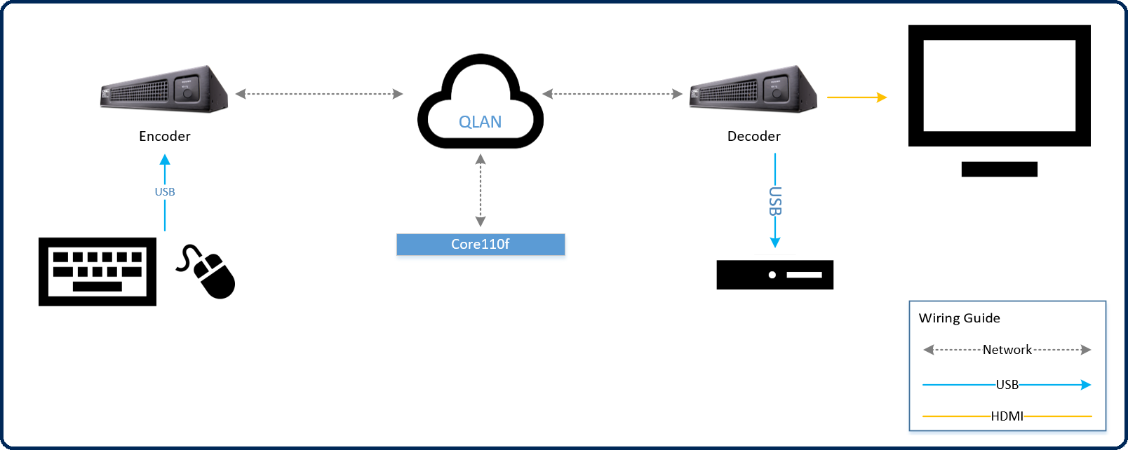
In this application, a user connects a keyboard and mouse to the NV-32-H Encoder at the table location. The HID signals from the keyboard and mouse are routed to the NV-32-H Decoder (via Q-SYS) and sent to the PC that is attached via USB. Here’s what that looks like in the Q-SYS Design:

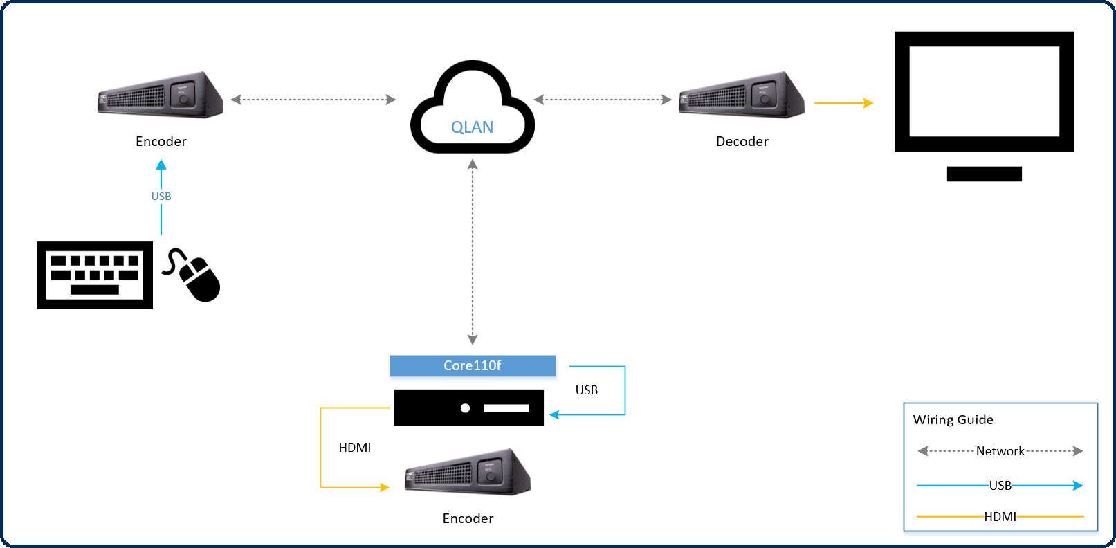
In this application, a user chooses to collocate the room PC in an IDF with the AV equipment. The video signal for the PC connects to an NV-32-H Encoder to route back into the room (to be displayed on the monitor, via an NV-32-H Decoder). For USB routing, the Encoder or Core 110f could be used to deliver the remote (in-room) keyboard and mouse to the PC in the IDF location. Here’s what that looks like in the Q-SYS Design:
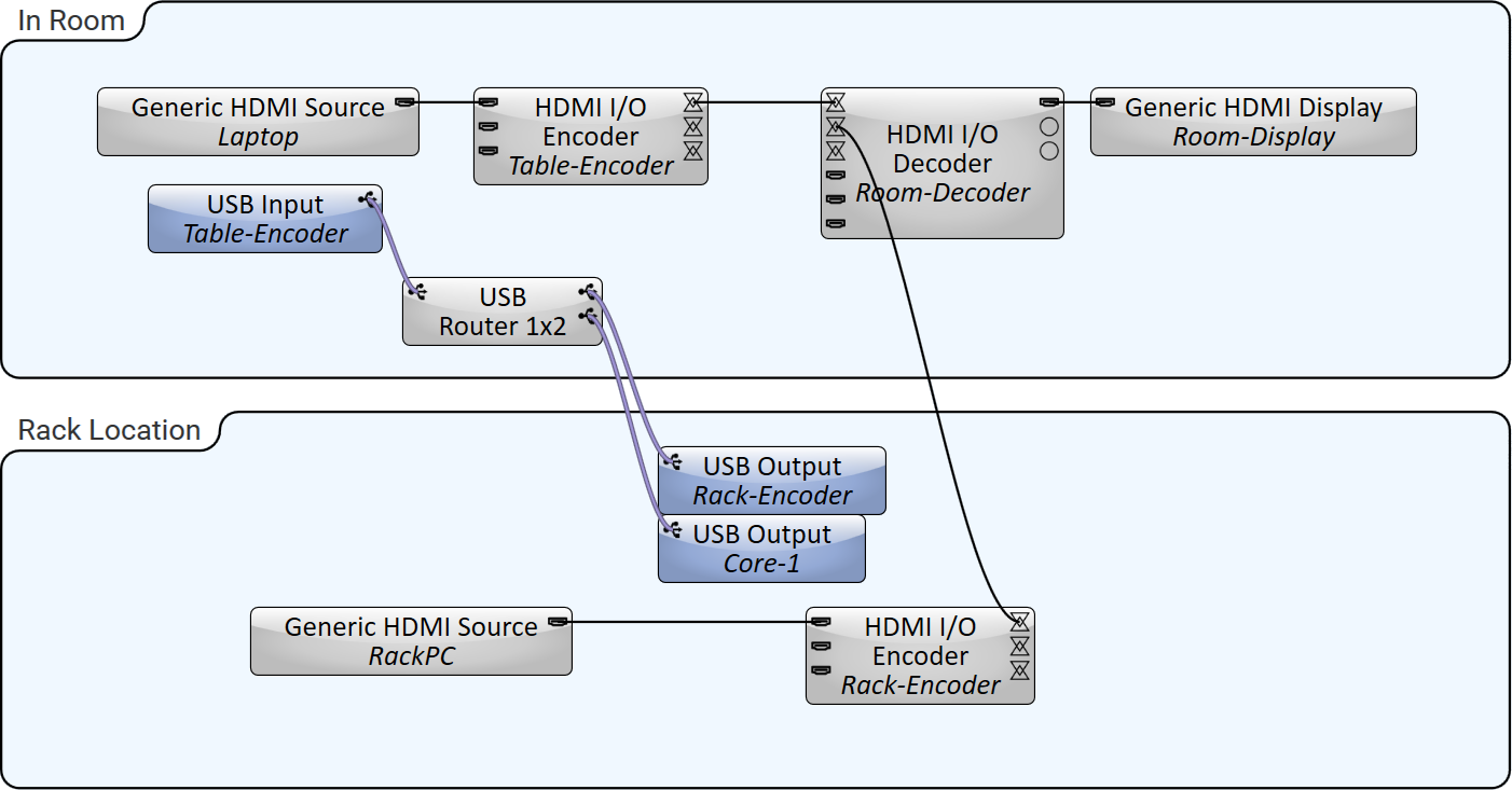
Note: This design allows for either the Core 110f or rack Encoder to deliver the keyboard and mouse to the rack PC. Note, however, that the signal cannot be routed to both peripherals at the same time.
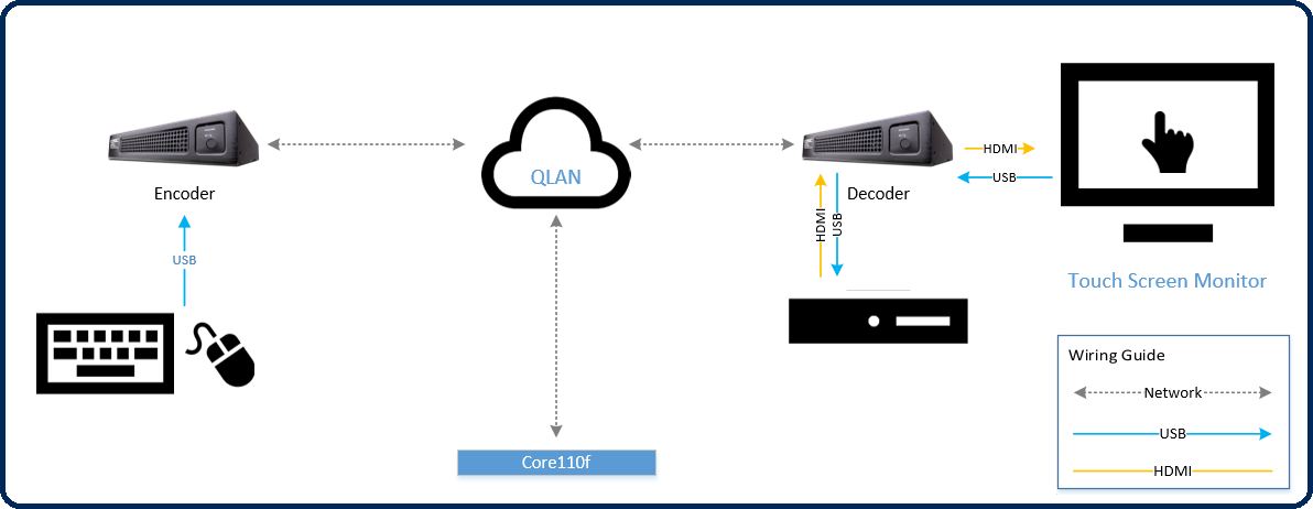
In this application, the touch screen monitor, as well as the keyboard and mouse in the room, is able to route HID signals over the Q-LAN network to the room PC. The PC receives its USB connection from the room Decoder. Here’s what it looks like in Q-SYS Designer:

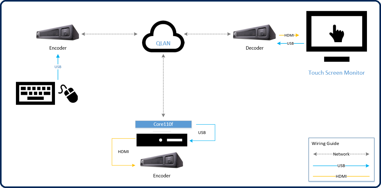
In this application, the touch screen monitor, as well as the keyboard and mouse in the room, is able to route HID signals over the Q-LAN network to the remote PC located in the IDF. The PC receives its USB connection from the Core 110f, but could just as easily receive it from the Encoder that is routing the video signal. Here’s what it looks like in Q-SYS Designer:
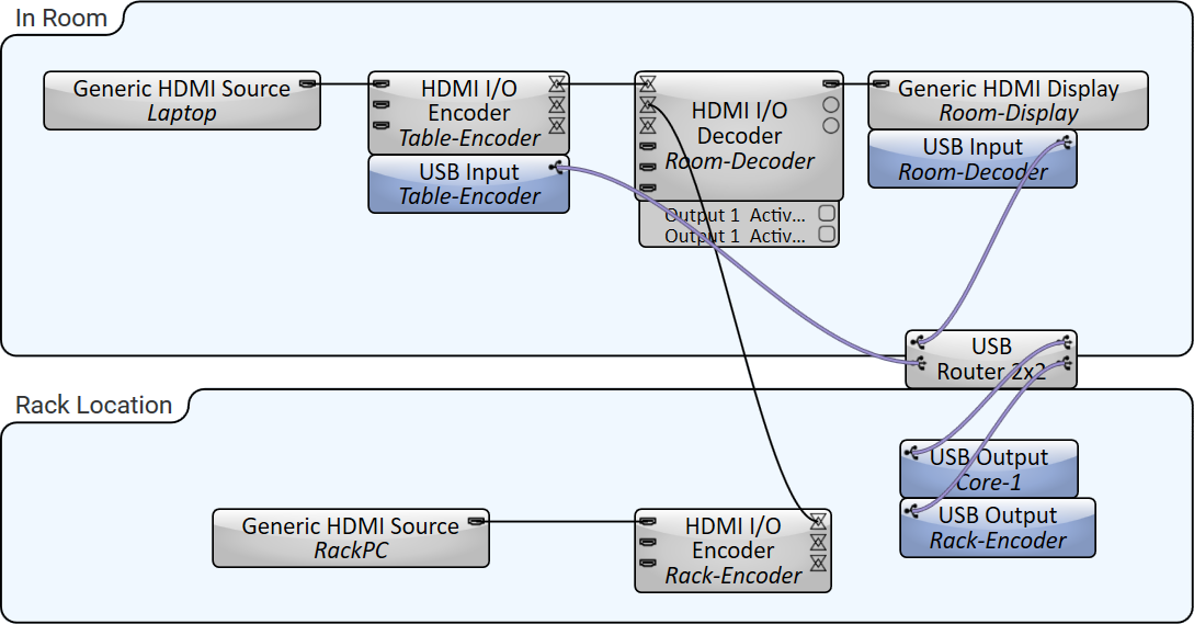
Note: As drawn, the input signal from the touch screen can be routed across the Q-LAN network to either the Encoder or Core 110f, but only one of those two outputs can be active at a time.
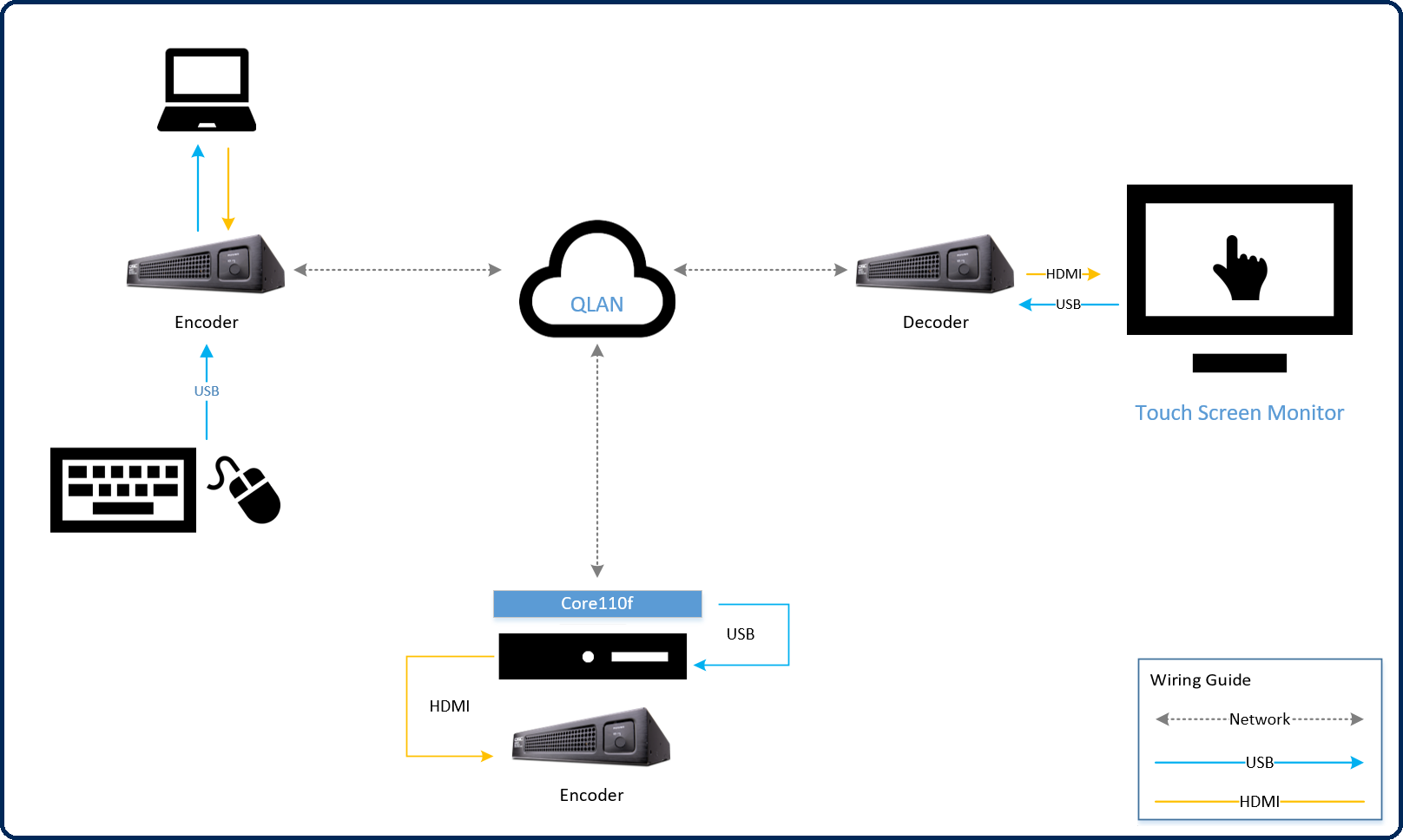
In this application, a touch screen monitor can send USB events to either the rack PC (in the IDF, connected to the Core 110f) or the laptop on the table (connected to the NV-32-H Encoder). Here’s what it looks like in Q-SYS Designer:
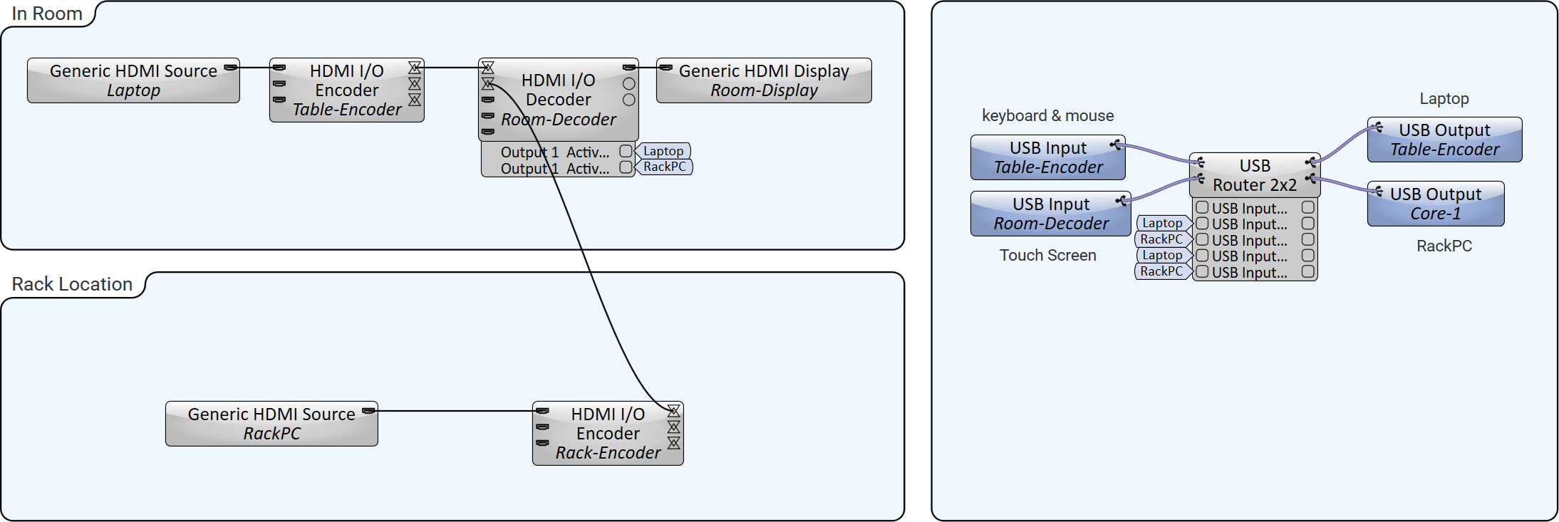
Note: Since USB events cannot be sent to two different hosts at the same time, the USB Router directs the output to one host or the other. This could even be automated based on what source is visible on the screen. For example, as drawn, a user could use the Active source control pin to tie the video source on the screen to the destination for the USB signals (keyboard and mouse + touchscreen). This does not require a scripting license.
Input Pins
USB Output 
This pin represents outgoing HID signals from Q-SYS hardware supporting USB routing to a USB host device. Wire this pin from a USB Output pin on the USB Router component or directly from the USB Input pin of the USB Input component of another Q-SYS hardware device.
Output Pins
This component has no output pins.
Tip: For additional properties that are not listed, refer to the Properties Panel help topic for more information.
This component has no configurable properties.
Status LED
This LED changes color to indicate the current status of the Component. See Status for the meanings of the various colors.
Status
Component status is conveyed with the Status LED and Status box, which uses both color and text to indicate the current condition:
- OK: The device is functioning normally.
- Initializing: The device is in the process of a firmware, patch, or configuration update, or the design is starting.
- Compromised: The device is functioning, but a non-fatal problem exists. Refer to the Status box for details.
- Missing: The device cannot be discovered.
- Fault: The device is malfunctioning or is not properly configured. Refer to the Status box for details.
- Unknown: This status appears during a Core reboot (for example, during a firmware update), or when a design is being uploaded to the Core and before it has started running.
- Not Present: If applicable to the device, this status appears when the device is not connected to the network and its Is Required component property is set to 'No'. This status also appears if the device component's Dynamically Paired property is set to 'Yes', pairing has not been assigned in Core Manager, and the device component's Is Required property is set to 'Yes'. See Dynamic Pairing.
|
Pin Name |
Value |
String |
Position |
Pins Available |
|---|---|---|---|---|
|
USB Output Status |
0 1 2 3 4 5 |
OK (Green) Compromised (Orange) Fault (Red) Not Present (Gray) Missing (Red) Initializing (Blue) |
- |
Output |
The USB Input and Output components support USB HID signals. This includes support for keyboard, mouse, and touch screen devices. You can also use the External USB Audio Device In and External USB Audio Device Out components to route USB audio signals.
No. Connect the HID device directly to the USB-A port on the Q-SYS device.
No. You can only route signals from USB HID devices – keyboards, mice, and touch screens. Use the External USB Audio Device In and External USB Audio Device Out components to route USB audio signals.
Yes, use the USB Router component to configure routing in your schematic.
Yes, the USB Router component allows for multiple devices to be routed to a single output/host. For example, a keyboard and mouse on a table, as well as a touch screen monitor on a wall, can be routed to a single remote PC.
No, an input device can only be routed to a single output (host) at a time. You can use the USB Router component's control panel to dynamically switch the routing from device to host, but cannot route to multiple outputs simultaneously.
