
Type 2 hardware provides new cables and connectors between the I/O cards and main boards in Cores and I/O Frames. Due to this change, the Type 2 hardware is not physically compatible with the older hardware. You can still integrate the new I/O Frames and Cores in the same system with older hardware, but the I/O cards are not interchangeable. Type 2 hardware can be identified by a yellow label on the back of the Core and I/O Frame, and the bottom of the I/O cards.
This topic covers the Core 1100, and Core 3100.
NOTE: This topic is for reference only. Refer to the Q-SYS Core 1100 | 3100 User Manual for installation instructions.
The Core is Q-SYS' central processing unit. The Core processes and routes all audio, controls peripheral devices, manages firmware updates to the peripheral devices, all via a 1-gigabit Ethernet network. The Core has one slot available to add one of an I/O card.
The Q-SYS Core processing is accomplished using Intel® Xeon microprocessors and Intel server motherboards running, QSC-developed DSP algorithms under a customized Linux operating system. In addition, Sharc DSP is employed for some ancillary chores in peripheral devices.
NOTE: When a Core is shipped, the I/O card that is installed in the Core at shipping, is noted on the shipping label.
When you purchase a multi-track upgrade, you must purchase one of the available media drive upgrades: MD-S, MD-M, or MD-L.
VIDEO TUTORIAL: Video presentation available online for Audio Tracks.
CAUTION: If you upgrade your hard drive, you will lose any files you had on the flash drive. Back up the files prior to upgrading.
|
Model |
Local Audio Channels |
NAC |
NAS |
AEC |
Core to Core Streaming |
Maximum Channels Out 1 |
|---|---|---|---|---|---|---|
|
Core 1100 |
64 x 64 |
256 x 256 |
256 x 256 |
96 |
256 x 256 |
2048 |
|
Core 3100 |
64 x 64 |
512 x 512 |
256 x 256 |
192 |
512 x 512 |
2048 |
1. Using maximum fan-out, with 16-channel I/O Frames2. At least 128 NACs, and up to 512 NACs when sending an average of 8 or more channels per network audio stream (NAS) |
||||||
NOTE: For more information on NACs and NASs, refer to Networked Audio Design or watch the VIDEO TUTORIAL on Audio Channels and Audio Streams.
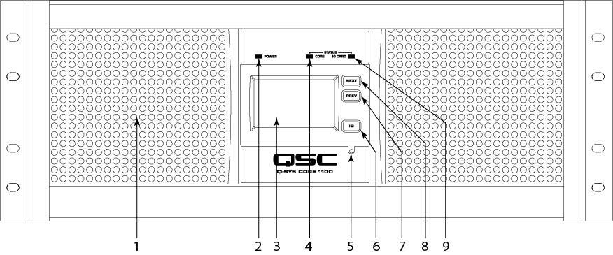
Front Panel Controls and Connections
|
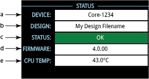
Status Screen
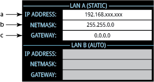
LAN A and B or AUX A and B
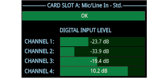
CARD SLOT A |
The Core 250i Type 2 allows eight of the following Type 2 I/O cards or a card/cover. Each I/O card supports four channels. The cards are not hot-swapable, and must be replaced by a qualified technician.
|
System Hardware |
Core 1100 / 3100 |
|||||||||||
|---|---|---|---|---|---|---|---|---|---|---|---|---|
|
Description |
System processor and control engine |
|||||||||||
|
Front Panel Controls |
LCD page Next momentary button LCD page Previous momentary button Unit ID momentary button Clear settings momentary switch (use a paperclip or similar tool to reset) |
|||||||||||
|
Front Panel Indicators |
Power On: Green LED Device Status: Tri-color LED I/O Card Status 480 x 240 Color Graphics LCD |
|||||||||||
|
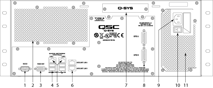
Rear Panel Connectors and controls |
RS-232: DE-9 (male 9-pin D shell connector) Video Out: DE-15 (female 15-pin high-density D shell connector) Auxiliary USB Ports x4 Q-SYS Network LAN A and LAN B: RJ45 1000 MBps only GPIO A and B: DA-15 (female 15-pin D shell connector) Auxiliary ports A and B RJ45 10/100/1000 MBps AC power connector Power switch |
|||||||||||
|
Capacity |
||||||||||||
|
|
|||||||||||
|
End Node Capacity |
|
|||||||||||
|
Processing (Channels of 32-bit audio) |
|
|||||||||||
|
I/O Capacity |
Up to 64 x 64 – Depends on I/O card purchased. |
|||||||||||
|
Line Voltage Requirements |
100 VAC - 240 VAC, 50 - 60 Hz |
|||||||||||
|
Dimensions (HWD) |
7" x 19" x 17.9" (177.8 mm x 482.6 mm x 454 mm) | |||||||||||
|
Accessories Included |
6 ft UL/CSA/IEC line cord Safety and Regulatory document, and Warranty Optional audio I/O ship kit |
|||||||||||
1. Using maximum fan-out with 16-channel unidirectional I/O Frames. |
||||||||||||
© 2009 - 2016 QSC, LLC. All rights reserved. QSC and the QSC logo are trademarks of QSC, LLC in the U.S. Patent and Trademark office and other countries. All other trademarks are the property of their respective owners.
http://patents.qsc.com.
![]()
 Related Topics