This topic describes the General Purpose Input Output (GPIO) hardware interfaces available in Q-SYS. Refer to the GPIO topic for information about configuring and controlling the GPIO interfaces in a Q-SYS system.
The General Purpose Input Output (GPIO) interface is used to integrate Q-SYS with custom or third-party controls. The GPIO allows you to control external hardware, control certain aspects of Q-SYS using external hardware. In addition, you can use the GPIO to supply an external word clock to Q-SYS for synchronization. Refer to the Core Status topic for details. The GPIO selections require an external TTL level word clock: pin 3 is signal, pin 8 is ground. When you select GPIO A-1 or GPIO B-1 as the clock source, the respective GPIO 1 Property changes to "Input used as clock source". The clock source should be connected to pin 3 of the respective GPIO connector - either GPIO A or GPIO B.
Note: Typically, Internal is used as the clock source. Only if there is a need to synchronize the Q-SYS system to an external clock would you use GPIO or AES3. You would use GPIO if the external clock signal is a word clock. You would use AES3 if the external clock signal is an AES3 signal. Often an AES3 signal without audio is used to reduce the clock jitter. This signal is called AES3 black.
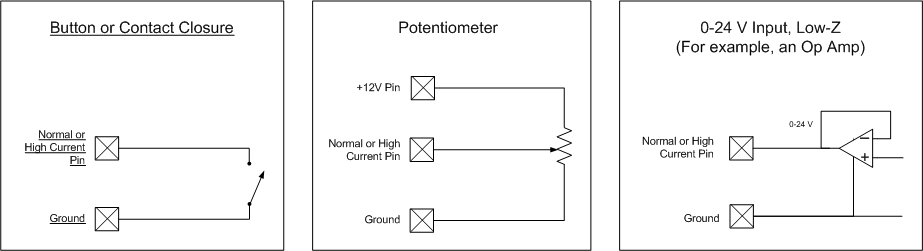
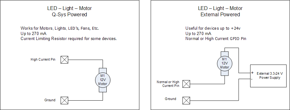
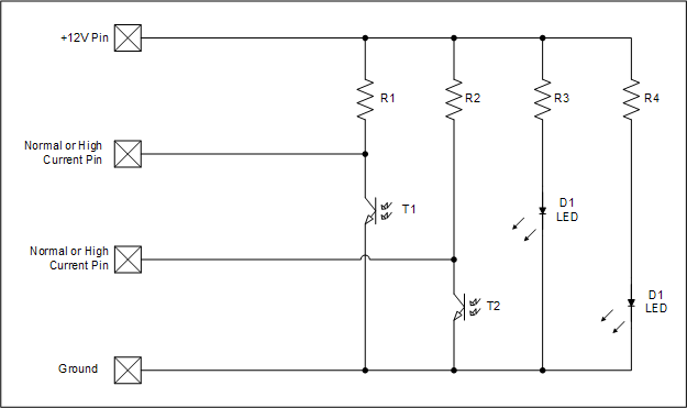
Some examples of hardware to which you can connect are: Potentiometers, buttons, switches, LED/lights, motors (including fans) relays, temperature and humidity sensors, etc.
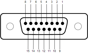
The GPIO interface is physical hardware, and is represented in Q-SYS Designer by the GPIO component. There are two GPIO interfaces available in a Core, and one in an I/O Frame. The external connection to the GPIO interface is supplied via a standard DA-15 connector. A GPIO component is configured in Q-SYS Designer (GPIO component Properties) where there are eight configurable pins that represent and configure GPIO-1 through GPIO-8 in the DA-15 connector. Refer to the GPIO Connector Pinout for more information.
The GPIO is protected by self-resetting fuses.
|
DB-15 Pin # |
Signal Name |
Signal Type |
Description |
|---|---|---|---|
|
1 |
RNO |
Relay Contact |
Relay Normally Open 1 |
|
2 |
RNC |
Relay Contact |
Relay Normally Closed 1 |
|
3 |
GPIO-1 |
Normal Current |
Configurable 2 |
|
4 |
GPIO-3 |
Normal Current |
Configurable |
|
5 |
Power |
Power |
+12 VDC |
|
6 |
GPIO-5 |
High Current |
Configurable |
|
7 |
GPIO-7 |
High Current |
Configurable |
|
8 |
GND |
Ground |
Ground |
|
9 |
RC |
Relay Common |
Relay Common 1 |
|
10 |
GND |
Ground |
Ground |
|
11 |
GPIO-2 |
Normal Current |
Configurable |
|
12 |
GPIO-4 |
Normal Current |
Configurable |
|
13 |
Power |
Power |
+12 VDC |
|
14 |
GPIO-6 |
High Current |
Configurable |
|
15 |
GPIO-8 |
High Current |
Configurable |
1. The GPIO Relay is controlled in a Q-SYS Design.2. When Using a Word Clock. The GPIO input impedance is much higher than what would normally be required to terminate a word clock signal. QSC recommends using a termination resistor between pin 3 and ground (pin 8 or 10). The resistor value should match the cable impedance. If the cable impedance is unknown, use 75 Ohm. Refer to the GPIO component for more information about external clocks. |
|||
| Specifications - Cores and I/O Frames | ||
|---|---|---|
|
Relay Pins |
Maximum Voltage, relative to Ground |
30 V |
|
Maximum Current through Relay |
1 Amp |
|
|
Power Pins |
Output Voltage |
11 V min 13 V max |
|
Maximum Output Current |
400 mA |
|
|
All Power and High Current pins combined |
Maximum Source Current |
400 mA |
|
All GPIO Pins 1 through 8 combined |
Maximum Sink Current |
1 A using 1 GND pin 2 A using 2 GND pins |
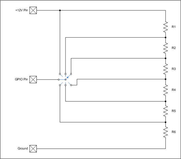
All resistors should have the same value. The total resistance should be about 10K Ohms. The individual resistor value should be 10,000 divided by the number of resistors. The schematic is an example only, and could easily be modified to have more switch positions or use multiple momentary buttons instead of a rotary switch.
Software and Firmware | Resources | QSC Self Help Portal | Q-SYS Help Feedback
Copyright © 2019 QSC, LLC. Click here for trademark and other legal notices. |
