This topic describes the General Purpose Input Output (GPIO) hardware interface for the Q-SYS IO-22. Refer to the IO-22 GPIO component topic for information about configuring and controlling the GPIO interface in a Q-SYS design.
The GPIO interface is used to integrate Q-SYS with custom or third-party controls. The GPIO allows you to control external hardware and certain aspects of Q-SYS using external hardware.
The GPIO interface is physical hardware, and is represented in Q-SYS Designer by the IO-22 GPIO component. A GPIO component is configured in Q-SYS Designer using the GPIO Properties where there are eight configurable pins that represent and configure pins D0 through D7 in the two Euro-style connectors.
The GPIO is protected by self-resetting fuses.
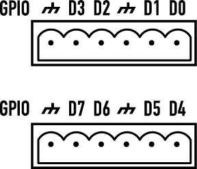
There are two 6-pin Euro-style connectors available on the rear of the unit. Pins D0 through D3 plus two grounds are on the top connector, D4 through D7 plus two grounds are on the lower connector. The table below shows the relationship between the physical pins, the Signal Name, and the Signal Type. When you configure the GPIO in Q-SYS Designer you will see the Signal Name, not the pin number. The Signal Type lists the choices you have for each of the Signal Names. All Signal Names have a digital in and digital out selection, and GPIO-2, GPIO-3, and GPIO-4 have clock signals.
|
Pin # |
Signal Name |
Signal Type |
Description |
|---|---|---|---|
|
D0 |
GPIO-1 |
Digital In / Out 1 |
|
|
D1 |
GPIO-2 |
Digital In / Out 1 or Sample Clock |
System Frequency 48 kHz |
|
|
GND |
Ground |
|
|
D2 |
GPIO-3 |
Digital In / Out 1 or Vector Clock |
3 kHz 6 kHz |
|
D3 |
GPIO-4 |
Digital In / Out 1 or Frame Clock |
Programmable - 30 Hz to 120 Hz Intended for Software debug. |
|
|
GND |
Ground |
|
|
D4 |
GPIO-5 |
Digital In / Out 1 |
|
|
D5 |
GPIO-6 |
Digital In / Out 1 |
|
|
|
GND |
Ground |
|
|
D6 |
GPIO-7 |
Digital In / Out 1 |
|
|
D7 |
GPIO-8 |
Digital In / Out 1 |
|
|
|
GND |
Ground |
|
1. Digital 1 = TTL 3.3 VDC @ 2 mA, Digital 0 = 0 |
|||
| Specifications - IO-22 | |
|---|---|
| Name | Specification |
|
Digital Input, Low |
0.8 V maximum |
|
Digital Input, High |
2.0 V minimum |
|
Digital Output, Low |
0.4 V maximum |
|
Digital Output, High |
2.4 V minimum, 3.3 V maximum |
|
Digital Output Impedance |
1 k ohm |
Software and Firmware | Resources | QSC Self Help Portal | Q-SYS Help Feedback
Copyright © 2019 QSC, LLC. Click here for trademark and other legal notices. |

