Open topic with navigation
I/O-8 Flex Channel Expander
The Q-SYS I/O-8 Flex Channel Expander adds several expansion capabilities to the Q-SYS platform.
- Eight flex channels (software configurable as either a Mic/Line input with phantom power, or a Line Level output)
- Audio-to-USB Bridging for integration with soft-codec applications for host PC
- Control connectivity via GPIO and RS232
- Versatile mounting accessories included
- PoE+ or external power supply (not included)
Refer to the I/O-8 Flex Component for Q-SYS Designer setup and operation.
Refer to the I/O-8 Flex User Manual for specifications.
I/O-8 Flex Front Panel
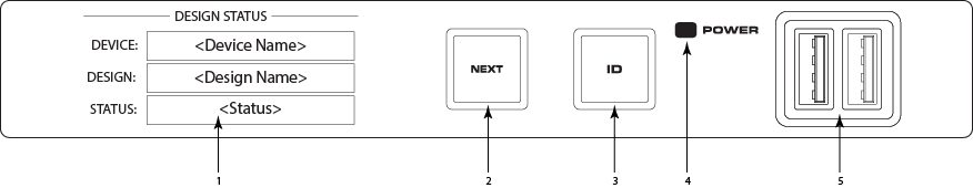
- OLED Display – Displays information about the I/O-8 Flex's settings and status.
- NEXT button – Cycles through the OLED information pages
- ID button – Locates the I/O-8 Flex in Q-SYS Designer GUI and Configurator
- POWER LED – Illuminates blue when the I/O-8 Flex is on
- USB Ports – USB Type A Host connectors (2)
I/O-8 Flex Rear Panel
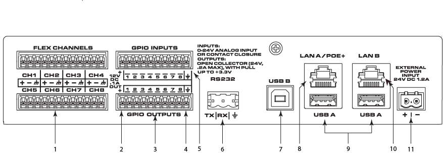
- Flex Channels – Eight user-configurable audio channels (mic/line input with optional phantom power or line output), balanced or unbalanced - blue connectors
- 12VDC, .1A OUT – The + connection uses the farthest left pins (not numbered) for both GPIO INPUTS and GPIO OUTPUTS
- GPIO OUTPUT – 8 outputs, open collector (24V, 0.2A maximum) with pull up to +3.3V (pins 1-8 equal pins 1-8 in the Q-SYS Designer GPIO Output component)
- Earth Ground – The ground connection uses the farthest right pins (not numbered) for both GPIO INPUTS and GPIO OUTPUTS
- GPIO INPUTS – 8 inputs, 0-24V analog input or contact closure (pins labeled 1-8 equal pins 1-8 in the Q-SYS Designer GPIO Input component)
- RS232 – Transmit and recieve, 3-pin, 5mm, Euro connector
- USB B – USB Type B Device connector
- LAN A/PoE+ – PoE+ power in, Q-LAN, control, VoIP, WAN streaming, AES67, etc., RJ45
- USB A – USB Type A Host connectors
- LAN B – Redundancy, Q-LAN, control, VoIP, WAN streaming, AES67, etc., RJ45
- EXTERNAL POWER INPUT 24VDC 1.2A – Auxiliary power, 24VDC, 1.2A, 2-pin, 5mm, Euro connector
