The General Purpose Input Output (GPIO) is used to integrate Q-SYS with custom or third-party controls. Using the GPIO Output you can control external hardware. With the GPIO Input, you can control certain aspects of Q-SYS using external hardware.
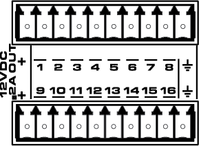
The GPIO pins in Q-SYS Designer are representative of the pins on the color-coded (black) Euro-style connector on the rear panel of the Core. The numbers stamped on the rear panel relate to the GPIO pins in Q-SYS Designer. Notice that the first and last pins on the top and bottom rows are not numbered: they are not GPIO pins.
The following table describes the controls available in the GPIO Input Control Panel.
|
Control |
Function |
Default / Range |
|---|---|---|
|
Digital Input |
This LED illuminates when there is a digital input on a GPIO pin. Each of the following Types of input has an LED to indicate a digital input is present:
|
Off / On |
|
Analog Input |
The analog input knob is provided when one of two Input Types is selected.
Both input voltages are displayed on a read-only knob control. |
|
|
Potentiometer Min Position Calibrate Min Max Position Calibrate Max |
The Potentiometer knob follows the position of the physical potentiometer connected to the GPIO pin. To calibrate Q‑Sys to the potentiometer:
If you know the values for Min Position and/or Max Position, you can enter them manually. |
N / A
|
|
Pullup Enable |
Provides a 5.11K Pullup resistor to +12VDC on the input pin when the Type is Raw. |
Off / On |
|
Property |
Function / Choices |
|
|---|---|---|
|
GPIO-1 to 16 |
Selects the Type of GPIO input
|
|
The available Control Pins depend on settings in Properties. Each of the following Control Pins are available on all GPIO Input pins.
|
Pin Name |
Value |
String |
Position |
Pins Available |
|---|---|---|---|---|
|
Digital Input |
0 1 |
false true |
0 1 |
Output |
|
Contact Closure |
0 1 |
false true |
0 1 |
Output |
|
Potentiometer |
0 to 1.00 |
0 to 1.00 |
0 to 1.00 |
Output |
|
Minimum Position 1 |
0 to 1.00 |
0 to 1.00 |
0 to 1.00 |
Input / Output |
|
Minimum Calibrate 1 |
0 1 |
false true |
0 1 |
Input / Output |
|
Maximum Position 1 |
0 to 1.00 |
0 to 1.00 |
0 to 1.00 |
Input / Output |
|
Maximum Calibrate 1 |
0 1 |
false true |
0 1 |
Input / Output |
|
Analog Input (Knob) |
0 to 24 | nn.nnnV | 0 to 1.00 | Output |
|
Raw |
|
|
|
|
|
Digital Input (LED) |
0 1 |
false true |
0 1 |
Output |
|
Analog Input (Knob) |
0 to 24 | nn.nnnV | 0 to 1.00 | Output |
|
Pullup Enable |
0 1 |
false true |
0 1 |
Output |
1. These control pins are selectable in the Control Pins list at the bottom of the GPIO selections. You must select the Type (Potentiometer or Raw) to make these Control Pins accessible. |
||||
Software and Firmware | Resources | QSC Self Help Portal | Q-SYS Help Feedback
Copyright © 2019 QSC, LLC. Click here for trademark and other legal notices. |
