The General Purpose Input Output (GPIO) Controller is used to integrate Q-SYS with custom or third-party controls. Using the GPIO Output you can control external hardware. With the GPIO Input, you can control certain aspects of Q-SYS using external hardware.
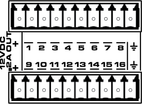
The GPIO pins in Q-SYS Designer are representative of the pins on the color-coded (black) Euro-style connector on the back panel of the Core. The numbers stamped on the rear panel relate to the GPIO pins in Q-SYS Designer. Notice that the first and last pins on the top and bottom rows are not numbered: they are not GPIO pins.
|
Control |
Function |
Default / Range |
|---|---|---|
|
Output |
This button supplies a 0 in the Off position and a 1 (3.3V TTL) in the On position. |
Off / On |
|
Pullup Enable |
Available when the Properties > Type is Raw. The Raw mode is for advanced capabilities. If there is something you cannot do in the standard choices, contact QSC Support for detailed information. |
Off / On |
Select one of the following for each of the 16 GPIO pins that you use.
|
Property |
Function |
|
|---|---|---|
|
Type |
Choices are:
|
|
The only Control Pin available under "Control Pins" in the Properties is Pullup Enable when you select Raw as the Type.
|
Pin Name |
Value |
String |
Position |
Pins Available |
|---|---|---|---|---|
|
Output |
0 1 |
false true |
0 1 |
Input |
|
Pullup Enable |
0 1 |
false true |
0 1 |
Input |
Software and Firmware | Resources | QSC Self Help Portal | Q-SYS Help Feedback
Copyright © 2019 QSC, LLC. Click here for trademark and other legal notices. |
