Cabling Requirements
Cabling for Q-SYS networks requires:
- 1000BASE-T gigabit Ethernet
- Category 5e cable
- 8P8C modular connectors (RJ45)
- ASNI/TIA-568-B.2 wiring pin-out
Topology Requirements
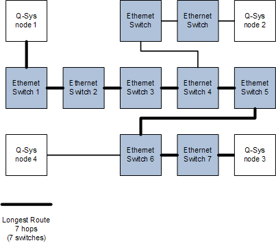
- No more than 7 hops between any two points with up to 100 meters between switches (Refer to the table below for more detail)
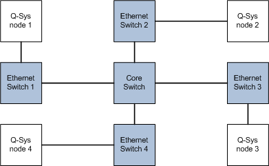
- Network diameter limit of 29 kilometers for three-hop Core-switched network
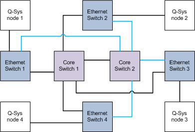
- Network diameter limit of 22 kilometers for four-hop redundant Core-switched network.
- Backbone bandwidth
- 1-Gigabit backbone bandwidth for systems not utilizing audio stream redundancy (no LAN B connections)
- 1-Gigabit backbone bandwidth on each network for installations using separate networks for redundancy
- 2-Gigabit backbone bandwidth required for installations using redundant connections to a single audio network
- No jumbo frames on any Q-LAN paths
Note: To measure the network diameter, measure between the two nodes with the longest physical path in the network.

Example Network Configurations
The following are general examples of networks meeting the network topology requirements. Other configurations are possible and would have different requirements based on the individual configuration.
Designers are free to use 10 Gigabit in place of 1 Gigabit while following the 1 Gigabit design rules.
Hop count is defined as how many switches there are between two system nodes.
Since all Q-SYS equipment is 1000BASE-T, the diameter of a 1-hop network is limited to 200 meters by the two 100 meter 1000BASE-T CAT-5e cables leading into the single Ethernet switch in a 1-hop scenario.
The maximum allowed diameter for a 2-hop network is 35 kilometers.
Note: The Q-SYS central processor is referred to as a Core. In this topic, "core" refers to the core switch in a network.
The longest path in this 3-hop core-switch configuration, for example, "Q-SYS node 1" -to- "Ethernet Switch 1" -to- "Core Switch" -to- "Ethernet Switch 2" -to- "Q-SYS node 2", can be no longer than 29 kilometers.

The longest path in this 4-hop core-switch configuration, for example, "Q-SYS node 1" -to- "Ethernet Switch 1" -to- "Core Switch 1" -to- "Core Switch 2" -to- "Ethernet Switch 2" -to- "Q-SYS node 2", can be no longer than 22 kilometers.

The maximum allowed diameter for a 5-hop network is 15 kilometers.
The maximum allowed diameter for a 6-hop network is 7 kilometers.
In the illustration below, between "Q-SYS node 1" to "Q-SYS node 3", there are 7 switches or hops. None of the cables in this configuration can be longer than 100 meters.

