Q-SYS Designer provides several tools and methods to help organize your design.
When you have a large design it can be difficult to tell which element you're looking at if you have many of the same elements in the design. Labeling the Schematic Elements can help reduce the confusion.
Some of the elements can be named through the Properties – for example, Q-SYS Cores and I/O Frames.
To rename a component in your schematic, select it and start typing. Alternatively, press the space bar to clear the existing name or Backspace to edit the existing name. Press Enter to commit the name change.
You can use the Graphic tools to label and group items in your Schematic.
You can identify buttons that have been placed in the Schematic or UCI by dragging a bitmap graphic file into the button. In addition, you can copy an object from a vector type graphic program into the Schematic, then drag it into a button. When it is placed into the button, the graphic is sized for the button. You cannot use an icon file (.ico).
The following tools are available in the Tools > Align menu and the right-click menu:
The following tools are available in the Tools > Distribute menu and the right-click menu:
The following tools are available in the Tools > Pack menu and the right-click menu:
You can select one or more Schematic Elements and drag them into the desired position. The following information describes tolls provided in Q-SYS to assist with alignment.
You can select one or more components and/or controls, and position them using numeric values available in the Position field of the component Properties.
You can select one or more controls and position and size them using numeric values available in the Size field of the Control Properties.
The positions are numbered from the upper left corner of the Schematic starting at zero (horizontal and vertical) to a maximum of 2000 (horizontal and vertical).
The maximum value is 2000 for both horizontal size and vertical size.
Note: When you have a control selected, and you have clicked in the Size Property for that control, you can adjust the vertical size of the selected control using the cursor up/down arrow keys.
When you place an item in the Schematic, it is placed in order in the Z axis, back to front. The newer items are in front of the older items. You can change that order using the following procedure.
You can order more than one item by selecting multiple items then using one of the methods above. When you do this, the selected items move to the front of all other items, but maintain the order between themselves.
Copy and pasting, or duplicating an item always places that item in the front just as adding an item from the Schematic Library, Inventory, or other.
Locking a Schematic Element allows you to maintain the position of elements in the design mode.
To lock a Schematic Element, select the Element or Elements you wish to lock, and from the main menu, select Tools > Lock, or right-click the component and select the lock icon.
To unlock all the locked items, from the main menu, select Tools > Unlock All, or right-click the component and select the unlock icon.
Note: Because you cannot select a locked item, you cannot unlock a single item from the main menu, it must be all. However, if you use the right-click method you can unlock the single item you right-clicked.
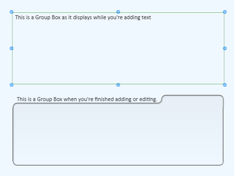
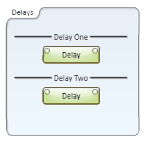
You can add Headers, Text Blocks, and Group Boxes to organize, annotate, and enhance the appearance of your design / User Control Interface using the following Graphic Tools. For complete information, see Graphic Tools.
If you have a list of items, or a set of sequential numbers, you can select the list/sequence and paste it into a group of Headers, Text Blocks, or Group Boxes. The list or sequence must be either tab delimited, or on separate lines (carriage returns).
Note: There are other methods of creating a list that can be pasted into Q-SYS boxes, and some that won't work. For example, you cannot paste a list from Microsoft Excel. However, if you copied the list from Excel into Microsoft Word, it becomes a table that you can paste into Q-SYS boxes. Other applications have not been tested.
You can add pictures and graphics from other applications to the Q-SYS Designer Schematic, or User Control Interfaces (UCI). Described below are some of the ways you can add various types of graphics.
When you bring a graphic into Q-SYS from another application it will always display behind any of the Q-SYS objects, i.e. Components, Links, and so on. If you bring in multiple graphics from other applications, the front to back order (z-order) is initially, the last one brought in is on top. If you save the design, then reopen it, the order may change. It is recommended that you do not use multiple graphics where the z-order is important, or that you merge the graphics in the order in which you want them before you bring them into Q-SYS.
Some of the bitmap file types you can use are .bmp, .png, .gif, .tif and, .jpg. You can add these file types by:
You can copy and paste vector type graphics from some applications in which they were created, to the Q-SYS Designer Schematic or UCIs.
You can also drag a vector-type file into Q-SYS as you can a bitmap file.
To organize and increase the overall size capability of your design schematic, Q-SYS supports multiple pages of schematics.
You can divide the Schematic Page area into multiple sections called Tab Groups. You can create Vertical and/or Horizontal Tab Groups add and/or delete Schematic Pages from a group and move pages between the groups. Tab Groups can be added or "ungrouped" in the Design, Emulate or Run modes.
Initially you must have more than one Schematic Page in your design. If you already have Tab Groups, you must have more than one Schematic Page in a Tab Group in order to create an additional group.
To add a Tab Group to your design:
You can create as many Tab Groups as you have tabs. Once you create a new Tab Group, you can add Schematic Pages to the group, and move pages from one group to another.
Each item that you can add to your Schematic has its own color assigned. There is no particular color coding scheme to the default colors assigned to the various items, but you can assign custom colors for your own purposes.
You can control the color Properties of only some items while they are in a Control Panel. An item can have one or more of the following color Properties:
Note: The eyedropper always copies the Fill color of an item. Some items, like a button, have multiple states, each having a different color. If the item is in a state where the Fill color is not visible, you still get the Fill color of the item, not the currently visible color.
Note: If you pass the eyedropper cursor over an open Control Panel, or anywhere outside of the Schematic, it changes to the standard cursor, but the eyedropper function is still Active.
In Q-SYS, buttons and LEDs have at least two states: binary 0 and 1, off and on. Each application of a button may have different text outputs that don't necessarily relate to Off / On, but work with 0/1. For example, an Invert button uses normal and inverted. For the purposes of selecting colors for buttons and LEDs, this topic uses 0 and 1 and off, on. The 0 (off) state is typically the default state of a button and uses a duller color than the 1 (on) state although both colors are in the same color range.
The control you want to color must not be in a Control Panel. You must drag the control from the Control Panel to either the Schematic or a User Control Interface (UCI) before you can change its color.
OR
Software and Firmware | Resources | QSC Self Help Portal | Q-SYS Help Feedback
Copyright © 2019 QSC, LLC. Click here for trademark and other legal notices. | Q-SYS 8.1.1