The Properties listed below are duplicated on RS-232 USB Video Bridge Status component. The other Properties available when the RS-232 Serial Port is selected are related to the USB Video Status component, and are listed in the individual Status topics.
|
Property |
Function |
Choices |
|---|---|---|
|
Name |
Text name identifying the RS-232 Serial Port component. |
User defined |
|
Location |
User-defined name that groups the Transmitter with other components in the same physical location, or in the same organizational scheme. The default is "IOUSB-xxxx". The four x's represent four unique alphanumeric characters. |
User-defined |
|
Is Required |
When Is Required is set to Yes, an error displays if the hardware does not exist on the network. This is the default behavior. When Is Required is set to No, the device is identified as not present, its status state is Not Present which is not considered an error. The color displayed for "Not Present" equipment is gray. If a device is dynamically assignable but has not been assigned, it is considered Not Present" even if it is required. |
Yes / No |
|
Serial Port |
Identifies which serial port you are communicating through. |
0 to 4 |
|
Control |
Function |
Default / Range |
|---|---|---|
|
TX Bytes |
Displays a running total of the number of bytes sent. |
N / A |
|
RX Bytes |
Displays a running total of the number of bytes received. |
N / A |
|
Reset |
Resets both TX Bytes and RX Bytes to zero. |
N / A |
The available Control Pins depend on settings in Properties.
|
Pin Name |
Value |
String |
Position |
Pins Available |
|---|---|---|---|---|
|
Reset |
Trigger |
Input/Output |
||
|
Receive Bytes |
Text Box |
Output |
||
|
Transmit Bytes |
Text Box |
Output |
||

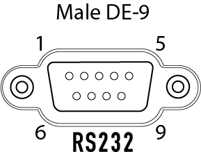
Pinout
- Pin 2 - RX (Receive)
- Pin 3 - TX (Transmit)
- Pin 5 - GND (Signal Ground)
- All other pins on a Core are not supported
- Pin 4 on an I/O-22 provides +5.5VDC @ 70mA (not on any other Q-SYS product, though)
This signal to DE-9 configuration is known as DTE. All 9-pin D-Shell RS-232 pinned as DTE have this configuration. All PC serial ports are DTE as is the Core, I/O-Frame and I/O-22. Usually peripherals are DCE, which reverses the receive and transmit pins, allowing a straight-thru cable to be used.
You must check the pinout of any equipment, including the cable, to be connected to a Q-SYS serial port for input or output. Many times in serial troubleshooting, problems may be solved by inserting a "null-modem" adapter or cable to swap the TX and RX pin positions. For custom terminated DE-9 connectors, pins 2 and 3 may need to be swapped on one end of the cable. In any case, a TX pin on one end MUST be connected to an RX pin on the other and vise-versa for data to flow properly
