Analog Out – DCIO/DCIO-H
The Analog Output provides line-level output for devices requiring line-level analog input. The Analog Output is physically a part of the DCIO and DCIO-H. The Analog Output converts the processed digital signal to analog and provides software controls before and after the convertor. Connections are made using two five-position Euro-style connectors.
Controls
The controls listed below are available on the Analog Output component in Q-SYS Designer. Each control listed in the Analog and Digital sections, are one per channel.
Channel
The following table provides descriptions of the channel labels relating to the controls in the control panel and the connector on the rear panel.
|
Control |
Function |
Default / Range |
|---|---|---|
|
HI |
Line output channel for hearing impaired. |
Rear Panel Connector 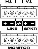
|
|
VI |
Line Output for visually impaired. |
|
|
Line |
Balanced line-level output at 14dBu. |
|
|
Spkr (Speaker) |
Powered output, 10 watts maximum, for a monitor loudspeaker. |
Analog
|
Control |
Function |
Default / Range |
|||
|---|---|---|---|---|---|
|
Peak Output Level (dBu) |
Measures Peak Output level to the output device for channels HI, VI, and Line. The Spkr output level is measured in Volts |
N / A |
|||
|
Relay Mute |
Mutes the output after the D-A converter and before the output. One button mutes all channels. |
Off / On |
|||
|
Max RMS Output Level (dBu) |
Controls the analog RMS output level after the D/A converter. This level is typically set slightly lower than the destination's sensitivity or maximum input level in order to avoid clipping the signal of a power amplifier. Varies in direct proportion with Output Gain. Not applicable for the Spkr channel. |
|
|||
|
Output Gain (dB) |
The amount of gain applied to the outgoing analog signal. Varies in direct proportion with the Max RMS Output Level. Not applicable for the Spkr channel. |
|
Digital
|
Control |
Function |
Default / Range |
|---|---|---|
|
Peak Output Level (dBFS) |
Measures the Digital Signal level prior to the D/A converter. |
Green = good Yellow = close to clipping Red = clipping |
|
Clip |
Red LED indicating if the signal is being clipped. |
Off / On |
|
Clip Hold |
When engaged, this holds the clip indication until manually cleared. |
Off / On |
|
Invert |
Inverts the audio signal. |
Off / On |
|
Mute |
Mutes the digital audio signal. |
Off / On |
|
Gain |
Controls the gain of the digital audio signal prior to the D / A converter. |
Default = 0 Range = -100 to +20 |
Status
|
Control |
Function |
Default / Range |
|---|---|---|
|
Status |
Component status is conveyed with the Status LED and Status box, which uses both color and text to indicate the current condition:
|
N / A |
Properties
There are no adjustable properties for the Analog Out component.
Control Pins
Amp (Spkr) Channel
The following Control Pin parameters are specific to the Amp (Spkr), Channel.
|
Pin Name |
Value |
String |
Position |
Pins Available |
|---|---|---|---|---|
|
Gain |
-100 to 20 |
-100dB to 20dB |
0 to 1.00 |
Input / Output |
|
Level (dBFS) |
-120 to 20 |
-120dB to 20dB |
0 to 1.00 |
Output |
|
Analog Level |
0 to 80 |
0V to 80V |
0 to 1.00 |
Output |
HI and VI Channels
The following Control Pin parameters are specific to the HI and VI Channels.
|
Pin Name |
Value |
String |
Position |
Pins Available |
|---|---|---|---|---|
|
Gain |
-100 to 20 |
-100dB to 20dB |
0 to 1.00 |
Input / Output |
|
Level (dBFS) |
-120 to 20 |
-120dB to 20dB |
0 to 1.00 |
Output |
|
Level (dBu) |
-120 to 24 |
-120dB to 24dB |
0 to 1.00 |
Output |
|
Max RMS Output Level (dBu) |
-42 to 18 |
-42.0dBu to +18dBu |
0 to 1.00 |
Output |
|
Output Gain |
-60 to 0 |
-60dB to 0dB |
0 to 1.00 |
Input / Output |
Line Channel
The following Control Pin parameters are specific to the Line Channel.
|
Pin Name |
Value |
String |
Position |
Pins Available |
|---|---|---|---|---|
|
Gain |
-100 to 20 |
-100dB to 20dB |
0 to 1.00 |
Input / Output |
|
Level (dBFS) |
-120 to 20 |
-120dB to 20dB |
0 to 1.00 |
Output |
|
Analog Level |
-120 to 24 |
-120dB to 24dB |
0 to 1.00 |
Output |
|
Max Level |
-46 to 14 |
-46.0dBu to +14dBu |
0 to 1.00 |
Output |
|
Output Gain |
-60 to 0 |
-60dB to 0dB |
0 to 1.00 |
Input / Output |
Common
The following Control Pins are common to all four channels.
|
Pin Name |
Value |
String |
Position |
Pins Available |
|---|---|---|---|---|
|
Clip (LED) |
0 1 |
false true |
0 1 |
Output |
|
Clip Hold |
0 1 |
false true |
0 1 |
Input / Output |
|
Invert |
0 1 |
normal invert |
0 1 |
Input / Output |
|
Mute |
0 1 |
unmute mute |
0 1 |
Input / Output |
|
Relay Mute |
0 1 |
unmute mute |
0 1 |
Input / Output |
|
Status |
0 1 2 3 4 |
OK (green) Compromised (orange) Fault (red) Unknown (red) Updating (blue) |
0 0.250 0.500 0.750 1.00 |
Output |
