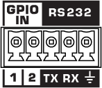
GPIO In (NV-32-H)
The NV-32-H Network Video Endpoint includes two General Purpose Input pins for extension of Q-SYS Control to third-party devices. In the Q-SYS Designer component properties, you can configure the input signal type for each pin – contact closure, digital, analog, potentiometer, or raw.
The GPIO In component represents the GPIO IN connection pins on the rear of the NV-32-H. Use one of the included 5-pin Euro connectors.
Note: On the NV-32-H, the RS-232 and GPIO IN pins share a 5-pin Euro connector. You can use both connection types simultaneously.

1, 2
Two inputs, 0-24 V analog input or contact closure. Pins 1-2 are the equivalent of pins 1-2 in the Q-SYS Designer GPIO In component.
Ground
Earth ground reference for GPIO input and RS-232 connections.
This component does not have standard input and output pins. See Control Pins.
Note: See the HDMI I/O (NV-32-H) topic for other NV-32-H properties.
GPIO-1, 2 Type
Select the type of GPIO input:
- Digital Input (TTL 3.3V)
- Contact Closure Input
- Potentiometer (10k Ohm, 12V)
- Potentiometer (2-wire)
- Analog Input (0-24V, low z)
- Raw
Digital Input
This LED illuminates when there is a digital input present on a GPIO pin. Supported Types:
- Digital Input (+3.3VDC)
- Contact Closure – When this Type is selected, the pin has approximately 9.5VDC present when the LED is lit.
- Raw
Analog Input
The analog input knob appears for these Types:
- Analog – allows a low impedance, 0 – 24VDC signal input
- Raw
Both input voltages are displayed on a read-only knob control.
Potentiometer: Min Position, Calibrate Min, Max Position, Calibrate Max
The Potentiometer knob follows the position of the physical potentiometer connected to the GPIO pin. To calibrate Q-SYS to the potentiometer:
- Turn the physical potentiometer to its minimum position.
- Click the Calibrate Min button. A value displays in the Min Position field.
- Turn the physical potentiometer to its maximum position.
- Click the Calibrate Max button. A value displays in the Max Position field.
If you know the values for Min Position or Max Position, you can enter them manually.
Pullup Enable
When enabled, provides a 5.11K pull-up resistor to +12VDC on the input pin when the Type is Raw.
|
Pin Name |
Value |
String |
Position |
Pins Available |
|---|---|---|---|---|
|
Digital Input |
0 1 |
false true |
0 1 |
Output |
|
Contact Closure |
0 1 |
false true |
0 1 |
Output |
|
Potentiometer Position |
0 to 1.00 |
0 to 1.00 |
0 to 1.00 |
Output |
|
Calibrate Maximum1 |
0 1 |
false true |
0 1 |
Input |
|
Calibrate Minimum1 |
0 1 |
false true |
0 1 |
Input |
|
Maximum Position1 |
0 to 1.00 |
0 to 1.00 |
0 to 1.00 |
Input / Output |
|
Minimum Position1 |
0 to 1.00 |
0 to 1.00 |
0 to 1.00 |
Input / Output |
|
Analog Input |
0 to 24 |
nn.nnnV |
0 to 1.00 |
Output |
|
Raw |
||||
|
Analog Input |
0 to 24 |
nn.nnnV |
0 to 1.00 |
Output |
|
Digital Input |
0 1 |
false true |
0 1 |
Output |
|
Pullup Enable2 |
0 1 |
false true |
0 1 |
Input |
1. Available in the Control Pins list when Type is set to Potentiometer.2. Available in the Control Pins list when Type is set to Raw. |
||||
