Core 250i, 500i
This topic provides information about the Q-SYS Core 250i and Core 500i.
Note: This product is discontinued. Reference the Core 510i replacement model. For Core 250i and Core 500i installation instructions, see the Hardware User Manual online.
Type 2 Hardware 
Type 2 hardware provides new cables and connectors between the I/O cards and main boards in Cores and I/O Frames. Due to this change, the Type 2 hardware is not physically compatible with the older hardware. You can still integrate the new I/O Frames and Cores in the same system with older hardware, but the I/O cards are not interchangeable. Type 2 hardware can be identified by a yellow label on the back of the Core and I/O Frame, and the bottom of the I/O cards.
Multi-Track Player (MTP) Upgrades
The available storage capability for audio files and design files depends on the Multi-Track Player option purchased with the Core. The MTP upgrade options use an upgraded media drive. (Available hard drive size varies.)
- Standard - 16 tracks
- Upgrade MTP-32 - 32 tracks
- Upgrade MTP-64 - 64 tracks
- Upgrade MTP-128 - 128 tracks
CAUTION: If you upgrade your hard drive, you will lose any files you had on the flash drive. Back up the files prior to upgrading.
Core Capacity
Refer to Networked Audio Design for Core capacity information.
Core 250i and 500i Front Panel
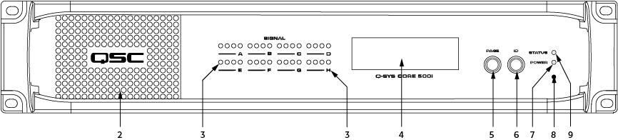
Front Panel Controls and Connections
- (N/A)
- Vents
- I/O Card Status (For 250i and 500i, there are eight sets of the following)
- Four tri-color LEDs, one for each channel: Green = good, Yellow = 3dB before clipping, Red = clipping, off = no audio.
- The AES3 card has four inputs, and four outputs. If you are using both inputs and outputs of an AES3 card, the LEDs display the input signal level. In order to display the output signal level, you must remove the AES3 Input component from the design.
- The CobraNet card uses the LEDs as follows:
- LED 1: activity (green) / fault (red) for primary port
- LED 2: in use (green) / conductor (yellow) primary port
- LED 3: activity (green) / fault (red) for secondary port
- LED 4: in use (green) / conductor (yellow) secondary port
- LED (behind the Letter "A", for 250i and 500i "A" through "H") Green = good, Red = bad, off = not present, or component not in current design schematic.
- LCD Readout - Use the Page button to navigate through the pages.
- Home
- NAME: name of the core
- DESIGN: name of the Q-SYS design
- STATUS: Running, Starting, Stopping, Idle, Internal Fault
- CARD SLOT (one of the following)
- None
- DataPort card
- AES3 Input / Output card
- Mic/Line In card
- Line Out card
- LAN A NETWORK SETTINGS
- IP ADDR:
- NETMASK:
- GATEWAY:
- LAN B NETWORK SETTINGS
- IP ADDR:
- NETMASK:
- GATEWAY:
- LAN AUX NETWORK SETTINGS
- IP ADDR:
- NETMASK:
- GATEWAY:
- ABOUT
- DEVICE MODEL: Q-SYS Core xxxx
- FIRMWARE VER:
- © QSC AUDIO PRODUCTS, LLC
- Home
- Page - LCD Navigation Button
- Identify Device
- On the Front Panel
- In Q-SYS Designer
- Power LED
- Factory Reset
- The following items are reset, or deleted to put the Core in the same condition as it was delivered from the factory.
- IP Addresses
- Hostname - Resets to "Core-<last 4 of MAC>"
- LAN A, LAN B, AUX A, and AUX B - All set to Auto. Any routing information is deleted.
- DNS - Not enabled. Any DNS IP Addresses are deleted.
- System Password and username - deleted
- Time Zone/Time/Date - reset to Mountain Time (Denver, Colorado)
- The Enable NTP check-box is unchecked, any manually entered NTP information is deleted.
- The following items are not removed on reset.
- Hardware ID
- Audio Files
- Up to the last four Q-SYS Designs, including the design that was running when the reset took place.
Insert a standard paperclip or other suitable tool into the pinhole and hold for 10 seconds to reset all network settings to their factory defaults.
- The following items are reset, or deleted to put the Core in the same condition as it was delivered from the factory.
- Device Status
- off - idle (not running a design)
- green - running
- amber - starting or stopping a design
- red - error
Core 250i Rear Panel
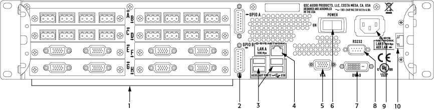
Rear Panel Controls and Connections
- Audio I/O - The Core 250i Type 2 allows up to eight Type 2 I/O cards and / or a slot cover (See Core 250i, 500i). The cards are not hot-swapable, and must be replaced by a qualified technician.
- GPIO (General Purpose Input Output)
- General Purpose Input / Output (GPIO) Controller (functionality/configuration, hardware)
- Two DA-15 connectors (female 15-pin D shell connector)
- USB Ports
- The USB ports are for future use.
- LAN-A Q-SYS 1 Gb Ethernet
- RJ45 connector - primary connection to the Q-LAN network.
- Streaming audio
- Control information
- Synchronization
- VGA Video Out
- Not supported. DE-15 (female 15-pin high-density D shell connector)
- AC Power Switch
- DVI-D Video Out
- Not supported
- RS-232 Serial Connector
- DE-9 (male 9-pin D shell connector)
- Serial Control for External Devices (CD / DVD Player, etc.) using a Lua Script. This is used in conjunction with the RS-232 Serial Port component, which is part of the Core component in Q-SYS Designer.
- Power Supply
- Dual power supply (not shown - optional)
- 90–132 or 180–264 VAC
- 47–63 Hz Auto-configuring
- IEC connector
- Cord Lock
- LAN-B/AUX port
- 1000 Mbps only, backup connection to Q-SYS gigabit network
Core 500i Rear Panel
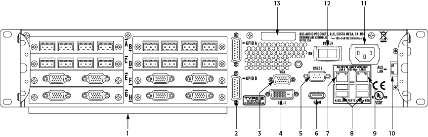
Rear Panel Controls and Connections
- Audio I/O - The Core 500i Type 2 allows up to eight Type 2 I/O cards and / or card covers (See Core 250i, 500i). The cards are not hot-swapable, and must be replaced by a qualified technician.
- GPIO (General Purpose Input Output)
- General Purpose Input / Output (GPIO) Controller (functionality/configuration, hardware)
- Two DA-15 connectors (female 15-pin D shell connector)
- VGA Video Out
- Not supported. DE-15 (female 15-pin high-density D shell connector)
- DVI-D Video Out
- Not supported
- RS-232 Serial Connector
- DE-9 (male 9-pin D shell connector)
- Serial Control for External Devices (CD / DVD Player, etc.) using a Lua Script. This is used in conjunction with the RS-232 Serial Port component, which is part of the Core component in Q-SYS Designer.
- HDMI Video Out
- Not supported
- LAN-A Q-SYS 1 Gb Ethernet
- RJ45 connector - primary connection to the Q-LAN network.
- Streaming audio
- Control information
- Synchronization
- USB Ports
- The four USB ports are for future use.
- LAN-B
- 1000 Mbps only, backup connection to Q-SYS gigabit network
- AUX LAN port
- The AUX A and AUX B network connections can be used for connecting to external control products. In general, these ports allow connection to a network that is separate from the LAN A/B audio and control networks for example, some facilities might want to keep a "control network" separate for various reasons. WAN Streaming can also be directed to use the AUX ports.
- Power Supply
- Dual power supply (not shown - optional)
- 90–132 or 180–264 VAC
- 47–63 Hz Auto-configuring
- IEC connector
- Cord Lock
- AC Power Switch
- Serial Number
Specifications
|
Core 250i |
Core 500i |
|
|---|---|---|
|
Description |
System processor and control engine |
|
|
Capacity |
||
|
Network Audio Channels |
||
|
In Out Max Ch Out1 |
In + Out 64 1024 |
In + Out 128 2048 |
|
End Node Capacity |
128 |
256 |
|
Processing (Channels of 32-bit audio) |
128 |
256 |
|
I/O Capacity2 |
Up to 32 channels. Requires purchase of I/O cards |
|
|
Line Voltage Requirements |
100 VAC - 240 VAC, 50 - 60 Hz |
|
|
Dimensions (HWD) |
3.5" x 19" x 15" (88.9 mm x 482.6 mm x 381 mm) |
|
|
Accessories Included |
6 ft UL/CSA/IEC line cord User Manual QSC Warranty Optional audio I/O ship kit |
|
1. Using maximum fan-out with 16-channel unidirectional I/O Frames.2. The CAES4 card (AES3 input/output) doubles the audio channel count of any slot in which it is used. |
||
For more information about discontinued Q-SYS products, including related documentation, see the Q-SYS / Legacy DSP page on the QSC website.
