I/O Frame 8s (Discontinued)
Note: This topic is for reference only. Refer to the I/O Frame 8s User Manual for installation instructions.
The I/O Frame 8s, running a customized Linux operating system, provides one of the main input and output connection devices for the Q-SYS system. The Core connects to the I/O Frame 8s via the Q-SYS network, limiting the number of I/O Frames only to the size of your Core, and network bandwidth. An I/O Frame 8s can contain up to eight of the available Audio I/O cards.
This topic covers the hardware aspect of the I/O Frame. For configuration details in Q-SYS Designer, refer to the I/O Frame configuration topic.
Note: When an I/O Frame is shipped, the I/O cards that are installed in the I/O Frame at shipping, are noted on the shipping label.
Type 2 Hardware 
Type 2 hardware provides new cables and connectors between the I/O cards and main boards in Cores and I/O Frames. Due to this change, the Type 2 hardware is not physically compatible with the older hardware. You can still integrate the new I/O Frames and Cores in the same system with older hardware, but the I/O cards are not interchangeable. Type 2 hardware can be identified by a yellow label on the back of the Core and I/O Frame, and the bottom of the I/O cards.
I/O Frame Front Panel
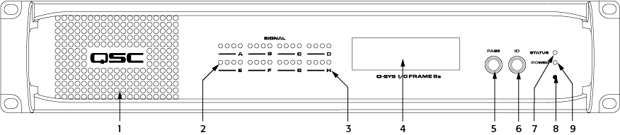
Front Panel Indicators and Controls
- Air Vents
- Audio Signal - Four tricolor LEDs, one for each channel, representing the digital audio level. Green = good, orange = 3 dB before clipping, red = clipping, off = no audio.
- The AES3 card has four inputs, and four outputs. If you are using both inputs and outputs of an AES3 card, the LEDs display the input signal level. In order to display the output signal level, you must remove the AES3 Input component from the design.
- The CobraNet card
- LED 1: activity (green) / fault (red) for primary port
- LED 2: in use (green) / conductor (yellow) primary port
- LED 3: activity (green) / fault (red) for secondary port
- LED 4: in use (green) / conductor (yellow) secondary port
- I/O Card Status - LED for each card slot letter (A, through H) indicates the card status. Green = good, Red = bad, off = not present, or not in current design schematic.
- LCD Readout
Five pages of information
- Status
- Name of I/O Frame
- Design name
- Status
- I/O card slot information - two pages listing all eight slots A - D / E - H and the type of I/O card in each slot
- LAN "A" information
- IP Address
- Network Submask
- Gateway
- LAN "B" information - same as above.
- About page
- Device model
- Firmware version
- Copyright information
- Status
- Page navigation button
- ID - Identify Device
- Front Panel
- Q-SYS Designer - Identifies this I/O Frame in the Q-SYS Designer design.
- Device Status
- off - idle (not running a design)
- green - running
- amber - starting or stopping a design
- red - error
VIDEO TUTORIAL: For a comparison of the Front and Back Panel with a Core, watch the video presentation of the Core and I/O Frame.
- Factory Reset
- Power LED
Scrolls through the LCD readout pages
Insert a paperclip or similar device into the reset hole and hold for 10 seconds. A timer displays on the LCD. This resets all network settings to their factory defaults: IP Addresses, hostname, etc.
I/O Frame Rear Panel
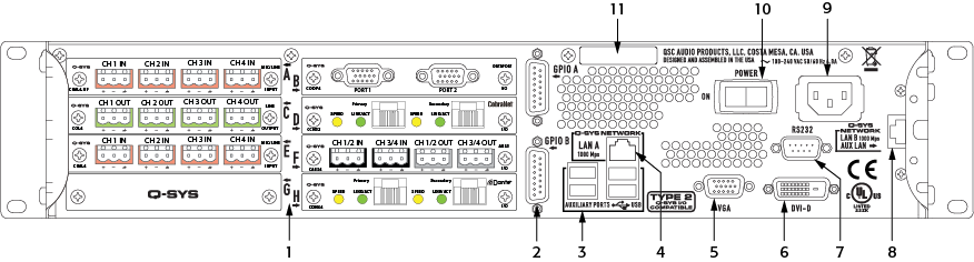
Rear Panel Connections
- Audio I/O Cards (1)
The I/O Frame allows for combinations of eight, of the following I/O cards.
Note: The types of cards shown in the example above are for illustration purposes only.
- Slot A – Mic/Line In card High Performance Version (Details: functionality/configuration, hardware)
- Slot B – DataPort card (Details: hardware, functionality/configuration)
- Slot C – Line Out card (Details: functionality/configuration, hardware)
- Slot D – CobraNet – (Details: functionality/configuration, hardware)
- Slot E – Mic/Line In card Standard Version (Details: functionality/configuration, hardware)
- Slot F – AES3 card (Details: functionality/configuration, hardware)
- Slot G – Blank Card
- Slot H – Dante card (Details: functionality/configuration, hardware)
- GPIO (x2)
- General Purpose Input / Output (GPIO) Controller (functionality/configuration and hardware), one DA-15 connector
- USB Type A (x4) – auxiliary ports
- LAN A – Primary Q-LAN Ethernet connection
- RJ45 connector
- Streaming audio
- Control information
- Synchronization
- VGA video out – For future use
- HD-15 female connector
- DVI digital video out – for future use
- DVI female connector
- RS-232
- Serial Control for External Devices (CD / DVD Player, etc.) using a Lua Script. This is used in conjunction with the RS-232 Serial Port component, which is part of the I/O Frame in Q-SYS Designer.
- LAN B – Backup (redundant) Q-LAN Ethernet connection
- RJ45 connector
- Streaming audio
- Control information
- Synchronization
- Power Supply (5)
- 90–132 or 180–264 VAC
- 47–63 Hz Auto-configuring
- IEC connector
- Cord Lock
- Power Switch – AC Mains disconnect
- Serial Number
Specifications
|
System Hardware |
I/O Frame |
|---|---|
|
Description |
System audio input and output device – eight I/O card slots. |
|
Front Panel Controls |
|
|
Front Panel Indicators |
|
|
Rear Panel Controls |
|
|
Rear Panel Connectors |
|
|
Capacity |
|
|
Local Audio Channels |
128 x 128 |
|
Network Audio Channels In |
128 |
|
Network Audio Channels Out |
128 |
|
Audio I/O Capacity |
Eight I/O Card Slots, Supporting: up to 32 analog I/O channels or up to 128 x 128 local digital I/O channels; Requires purchase of Q-SYS Type 2 audio I/O cards: CB, CIML4, CIML4-HP, COL4, CODP4, CAES4, CCN32, CDN64, CAN32. |
|
Line Voltage Requirements |
100 VAC - 240 VAC, 47 - 63 Hz |
| Current Draw |
Max 4.8 A @ 100 VAC |
|
Typical 1.9 A @ 100 VAC |
|
| Thermal | 650 BTU/h (typical) |
|
Dimensions (HWD) |
3.5" × 149" × 16.13" (88.9 mm × 482.6 mm × 425.7 mm) / 2RU |
|
Accessories Included |
|
