Signal Pins and Wiring in the Schematic
Overview
When a Schematic Element is placed in the Schematic, you can make virtual connections (in some cases representing physical connections) from one Schematic Element to another.
Connections can be audio, data, loudspeaker, or control type connections. When connecting the virtual components (proxies) representing physical hardware, it is extremely important to ensure the virtual connections match the actual physical connections.
There are three ways to wire components in Q-SYS Designer:
Traditional Wiring (click for details)
Signal Names (click for details)
Signal Snakes (click for details)
Other information contained in this topic:
Connection Types (click for details)
Traditional Wiring
You can use traditional type wires or Signal Names to connect components. The following section describes the use of traditional type wiring.
- Provides a quick visual representation of connections.
- You must select the connector(s) on one or more components and drag them to their destination.
- You must connect both ends of the wire, a loose wire is prohibited by the system.
- You can connect in either direction; from input to output, or output to input.
- You can customize the routing of wires (one at a time) to go around components, and so on.
- When you move a component, the wires move with it.
- If you delete the component, the wiring to the other component is removed.
- If you select either the wire or the pin to which a wire is connected, and press the Delete key, the wire is deleted.
- You cannot connect components on different Schematic Pages with wires. You must use Signal Names to do this.
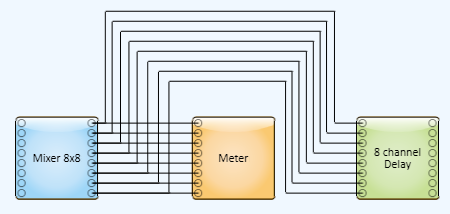
- Wires tend to clutter up the schematic, and in cases where there are many wires, it can be difficult to follow an individual wire unless you select it.
Wiring Tips for Schematic Elements
Q-SYS restricts the types of connections that you can make. For example, you cannot connect an input to an input, a control connector to a data connector, or a data connector of an amplifier to a data connector of another amplifier. The Schematic Elements you connect together is up to you as long as you're connecting the correct connection types and directions.
Wiring connections are made by selecting and dragging one or more of the connections on a Schematic Element to connections on one or more Schematic Elements.
Routing Wires
Physical wires can be difficult to route and organize, virtual wires are no different. In Q-SYS Designer you can add breakpoints to wires to help alleviate the problem.
- To create a breakpoint, select a single wire, hold the left mouse button down, and start dragging. The breakpoint is created.
- When a breakpoint is created, the wire is in a straight-wire mode, they no longer curve.
- Breakpoints create snap-guides as they pass connector pins, or other breakpoints.
- You can select multiple breakpoints and move them together.
- You can select breakpoints and delete them by pressing the Delete key.
- You cannot create multiple breakpoints at the same time.
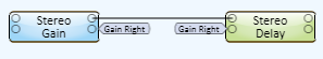
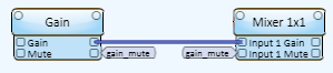
Signal Names
Signal Names provide the capability to assign user-defined names to signal pins (digital and analog audio, DataPort, and control) then use those names to connect to the next component without using wires. Signal Names allow for less cluttered schematics.
Creating Signal Names
When you use Signal Names, it is important to plan your naming conventions before starting in order to avoid confusion.
- Signal Names are not case sensitive.
- You can select one or more pins and simply type a name.
- You can select a Signal Name and type a new name.
- You can copy and paste Signal Names.
- You can name either the source or destination pins first.
- You can add Signal Names to pins that have traditional wires connected to them.
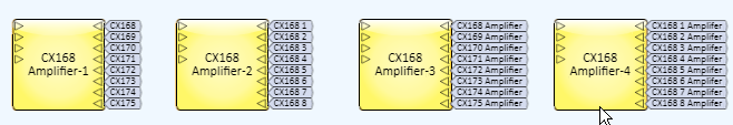
- Signal Names are numbered beginning with the last "number" you type. In the example below CX168 was entered by itself - the result is CX168, CX169, and so on. If you put a space after the 8, then enter the starting sequential number, for example, CX168 1, the result is CX168 1, CX168 2, and so on. Regardless of where the last number is in the name, it will be sequenced.
Using Signal Names
- You can use Signal Names across Schematic Pages.
- If you select a single signal pin that has a Signal Name, the Context Finder (Ctrl+F) popup displays a link to jump to the destination/source or, if you select a source pin with multiple destinations, it provides all the links.
- You can change the color of Signal Names to provide a quick visual representation of connections. If you set the color of a Signal Name, the Signal Name(s) associated with that Signal Name all change color.
- You cannot use source Signal Name (Signal Names connected to an output) in a Channel Group component.
- Single source (output) pin selected:
- You can type a name without a number, and the system does not number the name.
- If you type a name that is already used by another source pin, the system indicates an error. The name cannot be used.
- You can type a name and include a number that hasn't been used, and the system recognizes that as part of a sequence.
- Multiple source (output) pins selected:
- Duplicate source Signal Names are not permitted.
- When you start typing, a list of any previously assigned destination pins is presented from which you can choose. Or, you can simply type the name.
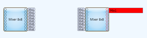
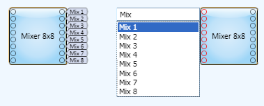
- You can type a name with no number and the Signal Names are automatically numbered starting with the lowest available number for that name. Mix becomes Mix 1 - n.
- You can type a name with a number and the Signal Names are automatically numbered starting with the number you typed, if available, and continuing until all the pins are numbered, or a duplicate source number is encountered.
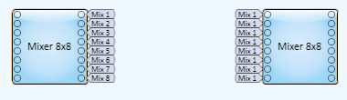
- Single destination (input) pin selected:
- You can type a name with no number, and no numbers are added by the system.
- You can type a name with a number included, and can make duplicates from that, or make it part of a sequence by selecting multiple pins, using the same name but the next number in sequence.
- If you have multiple destination pins with the same name, selecting one of those pins and renaming it causes all of the duplicates to be renamed. If you want to reassign an input pin to a different signal, delete the signal name from that pin and then create a new one.
- Multiple destination (input) pins selected:
- Duplicate destination Signal Names are permitted.
- When you start typing, a list of any previously assigned source pins is presented from which you can choose.
- If you choose a name from the list of source names, all the destination names created are duplicates of the one you selected. (One output going to multiple inputs.)
- If you type the name and include one of the existing source pin numbers, all the destination names are duplicates of the one you typed. (Same as selecting from the list.)
- If you type the name already in use, and do not include any numbers, the destination pins are numbered sequentially starting with the lowest source pin number. If there are no source pins with the same name, the numbering starts at one.
- If you type a name that hasn't been used, the pins are numbered sequentially.
Deleting Signal Names
- qxml To delete a Signal Name, select either the Signal Name itself, or the pin to which it is connected and press the Delete key.
- If a component, with Signal Names attached, is deleted, all the Signal Names are deleted.
Connecting Schematic Elements Between Schematic Pages
You can use Signal Names to connect Components on different Schematic Pages in the same way you use Signal Names on the same Schematic Page.
Signal Snakes
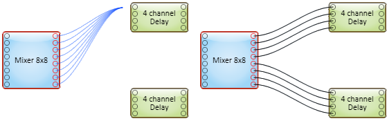
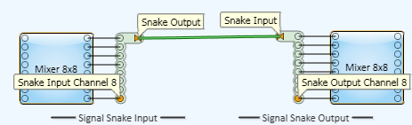
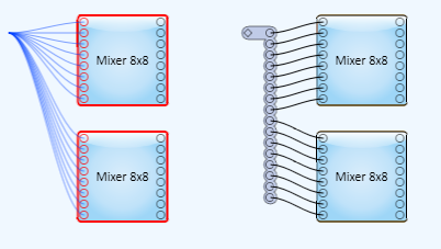
Signal Snakes provide the means to reduce a set of signals to a single graphical wire or named signal, similar to wrapping a number of wires into a bundle.
Signal Snakes are comprised of two components: a Signal Snake Input, and a Signal Snake Output. Signal Snakes can have from 1 to 256 channels, and the signal types of those channels can be mixed.
The number, type and order of the signal pins must match on a Signal Snake Input and Signal Snake Output that are to be wired together.
As with other wiring, Signal Snakes can be connected using a graphical wire and/or a Signal Name.
To Create Signal Snakes
- Select one or more pins on one or more components.
- Click one of the pins and begin dragging away from the component.
- Press the space bar. The Signal Snake is created.
OR
- Drag a Signal Snake Input and/or Signal Snake Output, from the Schematic Library > Layout section, into the Schematic.
- Manually wire the Signal Snakes to and from the desired components.
Or, you can copy and paste Signal Snakes.
Signal Snake Input or Output Properties
Select the following Properties:
- Fill
- Channel Count - can be any number from 1 to 256.
Signal Pin Types
Most of the Components you place in your design have Signal Pins of some type. The pins are distinguished by the shape of the pin. Each type of signal pin carries a different signal, and can only connect to the same type of pin.
Audio Signal Pins
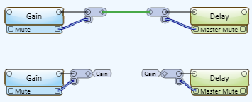
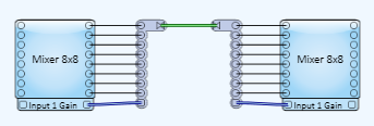
Audio signal pins are represented by a ( ) circle, and traditional wiring is represented by a thin black line. You can use Signal Names on audio signal pins.
The wiring between audio signal pins are the means by which the audio signal is passed from one DSP component to another. The number of signal pins, for most components, is variable and set in the component's Properties. Input (sink) pins are on the left, output (source) pins are on the right. Some components do not have both inputs and outputs.
Control Signal Pins
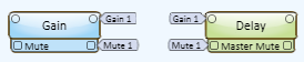
Control Pins represent the Controls available in the component's Control Panel. Control Pins are used to link controls between Schematic Elements, and link to/from Control Scripts. Control Pin signal pins are represented by a ( ) square, and the wiring is represented by a thick blue/white line. You can use Signal Names with Control Pins.
When you place a Schematic Element in the Schematic, none of the Control Pins are available, you must specify the Control Pins you want by clicking the associated checkbox under Properties > Control Pins. The Control Pins on the left side of the element are inputs, on the right side, outputs. Not all Controls of a component have both input and output Control Pins.
Examples:
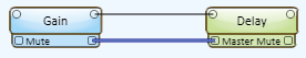
- You can link a mute button in a Gain component with the mute button in a Crossover component. When the mute button in the Gain control panel is activated, the mute button in the Crossover control panel is activated at the same time.
- When a Control Pin is linked to an input of a Control Script, and the Control associated with the Control Pin changes, the script performs the actions specified in the script.
- Control Pins can be linked to a monitoring device.
- Control Pins generally have three types of inputs and outputs:
- Value: The value of a control is numeric only, can be negative or positive, contain decimal fractions. For example, if you looked at the output of a Frequency control, on its Control Pin, the value range can be from 10 to 20,000.
- String: The string output of a control can contain a number plus its unit of measure. For example, if you looked at the output of a Frequency control, on its Control Pin, the string range can be from 10 Hz to 20 kHz.
- Position: The position output of a control is always 0 to 1.00. Binary controls produce a 0 and 1.00 output. Array type controls, like a drop-down list, produce positional numbers based on the number of available choices. If there are eight choices, the positional values start with 0, then 0.143, 0.286, up to 0.857 then 1.00 in even increments. Other controls like a Frequency knob produce numeric outputs starting with 0, then 0.001 up to 0.999, then 1.00.
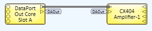
DataPort Signal Pins
Data type signal pins are represented by a right-pointing ( ) triangle, and the wiring is represented by a thick black/white line. You can use Signal Names with DataPort signal pins.
Data signal pins are proxies for physical connectors. They are called Data signal pins because they are on DataPort cards (in a Core or an I/O Frame), and DataPort amplifiers, and are used to pass audio, control signals, and telemetry information between Q-SYS and the DataPort amplifiers. In the physical world, the connection is made with DE-15HD connectors and cable.
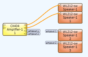
Loudspeaker Signal Pins and Wiring
Loudspeaker signal pins are represented by a left-pointing ( ) triangle, and the wiring is represented by a thin orange line. You can use Signal Names with loudspeaker signal pins.
Loudspeaker signal pins are proxies for physical connectors on QSC DataPort amplifiers and Loudspeakers.
Page Station Control Pins
Page Station Control pins carry control type signals unique to a Q-SYS Paging System. They are found on Page Station Components (proxies for the hardware), Virtual Page Station Components, and the PA Router to which both of the Page Station Components connect. The pin is represented by a down-pointing  triangle.
Signal Snake Pins
Signal Snake pins are unique; they change based on the type of pin to which they are connected.
- The exceptions are the Snake Input and Snake Output pins which are represented by the following polygon.

- The Input and Output Channels, prior to making any connections, are represented by a diamond shape
 .
.
