GPIO In (Core 8 Flex, I/O-8 Flex )
The General Purpose Input/Output (GPIO) connections allow the Q-SYS network to interface with miscellaneous outside devices, such as LED indicators, switches, relays, and potentiometers, and with custom or third-party controls. With the GPIO In, you can control certain aspects of Q-SYS using external hardware.
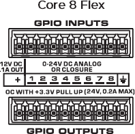
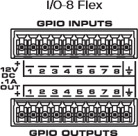
The GPIO pins in Q-SYS Designer are representative of the pins on the color-coded (typically black) Euro-style connector on the rear panel of the device. The numbers stamped on the rear panel relate to the GPIO pins in Q-SYS Designer. The first and last pins are not numbered as they are not GPIO pins but a DC reference voltage and ground, respectively.
The GPIO In component provides configuration and control of the inputs side for the GPIO found on the processor.
Note: Refer to the Using GPIO Inputs and Outputs technical note on the QSC website to learn how to configure GPIO on the I/O-8 Flex.
The GPIO allotment on the Core 8 Flex and I/O-8 Flex totals eight inputs and eight outputs. Configure each independent input and output in the Properties pane.
Flanking each row of eight GPIO inputs and outputs is a +12V DC terminal and a ground or reference terminal that can be used for potentiometers (input), relay coils and LEDs (output), and other uses. The +12V pins use a self-resetting fuse and each has up to 100 mA available.
Tip: For additional properties not listed, refer to the Properties Panel help topic for more information.
GPIO 1-8 Type
GPIO Type 1-8
Select the Type of GPIO input:
- Digital Input (TTL 3.3V)
- Contact Closure Input
- Potentiometer (10k Ohm, 12V)
- Potentiometer (2-wire)
- Analog Input (0-24V, low z)
- Raw
The Controls seen depends on the GPIO configuration in the Properties.
Digital Input (LED)
This LED illuminates when there is a digital input on a GPIO pin. Each of the following Types of input has an LED to indicate a digital input is present:
- Digital Input (+3.3VDC)
- Contact Closure – When this Type is selected, the pin has approximately 9 to 10VDC present when the contact is open (or nothing is connected) and the LED is off. When the contact is closed (pin is shorted to ground), the LED is on.
- Raw
Analog Input (Knob)
The analog input knob is provided when one of two Input Types is selected.
- Analog – allows a low impedance, 0 – 24VDC low z signal input
- Raw
Both input voltages are displayed on a read-only knob control.
Potentiometer - Min Position, Calibrate Min, Max Position, Calibrate Max
The Potentiometer knob follows the position of the physical potentiometer connected to the GPIO pin. To calibrate Q‑SYSto the potentiometer:
- Turn the physical potentiometer to its minimum position.
- Click the Calibrate Min button. A value displays in the Min Position field.
- Turn the physical potentiometer to its maximum position.
- Click the Calibrate Max button. A value displays in the Max Position field.
If you know the values for Min Position and/or Max Position, you can enter them manually.
Pullup Enable
Provides a 5.11K Pullup resistor to +12VDC on the input pin when the Type is Raw.
The available Control Pins depend on settings in Properties. Each of the following Control Pins are available on all GPIO In pins.
|
Pin Name |
Value |
String |
Position |
Pins Available |
|---|---|---|---|---|
|
Digital Input (LED) |
0 1 |
false true |
0 1 |
Output |
|
Contact Closure |
0 1 |
false true |
0 1 |
Output |
|
Potentiometer |
0 to 1.00 |
0 to 1.00 |
0 to 1.00 |
Output |
|
Minimum Position1 |
0 to 1.00 |
0 to 1.00 |
0 to 1.00 |
Input / Output |
|
Calibrate Minimum1 |
0 1 |
false true |
0 1 |
Input / Output |
|
Maximum Position1 |
0 to 1.00 |
0 to 1.00 |
0 to 1.00 |
Input / Output |
|
Calibrate Maximum1 |
0 1 |
false true |
0 1 |
Input / Output |
|
Analog Input (Knob) |
0 to 24 |
nn.nnnV |
0 to 1.00 |
Output |
|
Raw |
||||
|
Pullup Enable |
0 1 |
false true |
0 1 |
Output |