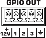
GPIO Out (NV-32-H)
The NV-32-H includes three General Purpose Output pins for extension of Q-SYS Control to third-party devices. In the Q-SYS Designer component properties, you can configure the output signal type for each pin – digital, open collector, or raw.
The GPIO Out component represents the GPIO OUT connection pins on the rear of the NV-32-H. Use one of the included 5-pin Euro connectors.

+12V
12 V, 0.2 A output.
1, 2, 3
Three outputs, user-configurable in the component GPIO Out (NV-32-H). Pins 1-3 are the equivalent of pins 1-3 in the Q-SYS Designer GPIO Out component.
Ground
Earth ground reference for GPIO output connections.
Output
This button sends a 0 in the Off position and a 1 (3.3V TTL) in the On position.
Invert
This button is available when the Type is Raw.
|
Pin Name |
Value |
String |
Position |
Pins Available |
|---|---|---|---|---|
|
Output (Digital Output, Open Collector, Raw) |
0 1 |
false true |
0 1 |
Input |
|
Invert1 |
0 1 |
false true |
0 1 |
Input / Output |
1. Available in the Control Pins list when Type is set to Raw. |
||||
Q-SYS device GPIO output states are undefined during boot-up and design redeploy. In the following table, "While On" and "While Off" indicate the button setting as defined in the running design file. During a reboot or redeploy, the setting may toggle depending on the GPIO type before returning to the defined setting after the design starts running.
Bold text indicates a temporary GPIO setting during boot-up and redeploy.
NV-32-H GPIO
|
GPIO Type |
While On |
While Off |
|---|---|---|
|
Digital Output |
Toggles to Off |
Stays Off |
|
Open Collector |
Stays On |
Toggles to On |
|
Raw |
Toggles to Off |
Stays Off |
