Core 1100, 3100
This topic provides information about the Q-SYS Core 1100 and Core 3100.
Note: This product is discontinued. Reference the Core 5200 replacement model. For Core 1100 and Core 3100 installation instructions and specs, see the Discontinued Products page.
Type 2 Hardware 
Type 2 hardware provides new cables and connectors between the I/O cards and main boards in Cores and I/O Frames. Due to this change, the Type 2 hardware is not physically compatible with the older hardware. You can still integrate the new I/O Frames and Cores in the same system with older hardware, but the I/O cards are not interchangeable. Type 2 hardware can be identified by a yellow label on the back of the Core and I/O Frame, and the bottom of the I/O cards.
Multi-Track Player (MTP) Upgrades
The available storage capability for audio files and design files depends on the Multi-Track Player option purchased with the Core. The MTP upgrade options use an upgraded media drive. (Available hard drive size varies.)
- Standard - 16 tracks
- Upgrade MTP-32 - 32 tracks
- Upgrade MTP-64 - 64 tracks
- Upgrade MTP-128 - 128 tracks
CAUTION: If you upgrade your hard drive, you will lose any files you had on the flash drive. Back up the files prior to upgrading.
|
Model |
Local Audio Channels |
NAC |
NAS |
AEC |
Core to Core Streaming |
Maximum Channels Out 1 |
|---|---|---|---|---|---|---|
|
Core 1100 |
64 x 64 |
256 x 256 |
256 x 256 |
72 |
256 x 256 |
2048 |
|
Core 3100 |
64 x 64 |
512 x 512 |
256 x 256 |
144 |
512 x 512 |
2048 |
1. Using maximum fan-out, with 16-channel I/O Frames2. At least 128 NACs, and up to 512 NACs when sending an average of 8 or more channels per network audio stream (NAS) |
||||||
Note: For more information on NACs and NASs, refer to Networked Audio Design
Core 1100 and 3100 Front Panel

Front Panel Controls and Connections
|
Status Screen
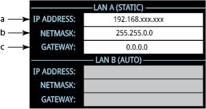
LAN A and B or AUX A and B
CARD SLOT A |


Core 1100 and 3100 Rear Panel
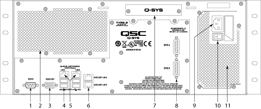
Rear Panel Controls and Connections
- RS-232 Serial Connector
- DE-9 (male 9-pin D shell connector)
- Serial Control for External Devices (CD / DVD Player, etc.) using a Lua Script. This is used in conjunction with the RS-232 Serial Port component, which is part of the Core component in Q-SYS Designer.
- Air Vents
- VGA Video Out
- Not supported. DE-15 (female 15-pin high-density D shell connector)
- USB Ports
- The USB ports are for future use.
- LAN-A and LAN B Q-SYS 1 Gb Ethernet
- RJ45 connector - LAN A is the primary connection to the Q-LAN network, LAN B is for redundancy.
- Streaming audio
- Control information
- Synchronization
- AUXILIARY LAN A and AUXILIARY LAN A ports
- 1000 Mbps only
- Audio I/O The Core allows one I/O card. The card is not hot-swapable, and must be replaced by a qualified technician.
- AES3 card (Details: functionality/configuration, hardware)
- Blank Card / Cover - is required if there is no I/O Card installed.
- CobraNet card (Details: functionality/configuration, hardware)
- Dante card (Details: functionality/configuration, hardware)
- DataPort card (Details: functionality/configuration, hardware)
- Line Out card (Details: functionality/configuration, hardware)
- Mic/Line In card High Performance Version (Details: functionality/configuration, hardware)
- Mic/Line In card Standard Version (Details: functionality/configuration, hardware)
- GPIO (General Purpose Input Output)
- General Purpose Input / Output (GPIO) Controller (functionality/configuration, hardware)
- Two DA-15 connectors (female 15-pin D shell connector)
- Power Supply
- Dual power supply (not shown - optional)
- 90–132 or 180–264 VAC
- 47–63 Hz Auto-configuring
- IEC connector
- Cord Lock
- AC Power Switch (AC Mains Disconnect)
- Air Vents
Specifications
|
System Hardware |
Core 1100 / 3100 |
|||||||||||
|---|---|---|---|---|---|---|---|---|---|---|---|---|
|
Description |
System processor and control engine |
|||||||||||
|
Front Panel Controls |
LCD page Next momentary button LCD page Previous momentary button Unit ID momentary button Clear settings momentary switch (use a paperclip or similar tool to reset) |
|||||||||||
|
Front Panel Indicators |
Power On: Green LED Device Status: Tricolor LED I/O Card Status 480 x 240 Color Graphics LCD |
|||||||||||
|
Rear Panel Connectors and controls |
RS-232: DE-9 (male 9-pin D shell connector) Video Out: DE-15 (female 15-pin high-density D shell connector) Auxiliary USB Ports x4 Q-SYS Network LAN A and LAN B: RJ45 1000 MBps only GPIO A and B: DA-15 (female 15-pin D shell connector) Auxiliary ports A and B RJ45 10/100/1000 MBps AC power connector Power switch |
|||||||||||
|
Capacity |
||||||||||||
|
|
|||||||||||
|
End Node Capacity |
|
|||||||||||
|
Processing (Channels of 32-bit audio) |
|
|||||||||||
|
I/O Capacity |
Up to 64 x 64 – Depends on I/O card purchased. |
|||||||||||
|
Line Voltage Requirements |
100 VAC - 240 VAC, 50 - 60 Hz |
|||||||||||
|
Dimensions (HWD) |
7" x 19" x 17.9" (177.8 mm x 482.6 mm x 454 mm) | |||||||||||
|
Accessories Included |
6 ft UL/CSA/IEC line cord Safety and Regulatory document, and Warranty Optional audio I/O ship kit |
|||||||||||
1. Using maximum fan-out with 16-channel unidirectional I/O Frames. |
||||||||||||
For more information about discontinued Q-SYS products, including related documentation, see the Q-SYS / Legacy DSP page on the QSC website.