Command Buttons
The Command Buttons component gives you up to 64 buttons to which you can assign a command string that is sent when the button is pressed. You can send the commands via TCP, UDP, or Serial (RS-232).
Inputs and Outputs
Control components do not have traditional input and output pins. If Control Pin is available for the component, an input or output will appear.
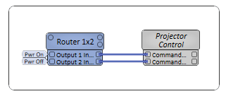
Control Pins represent the controls available in the component's Control Panel. Control Pins are used to link controls between Schematic Elements, and link to / from Control Scripts. Control Pin signal pins are represented by a  square, and the wiring is represented by a thick blue / white line.
In this example, we are using the Command Button component to control the Projector's Power On and Power Off function.

Command Button Properties
Type
Select a communication method: TCP(default), UDP, or Serial.
Command Count
Select the number of command lines, from 1 to 64 (default is 8).
Graphic Properties
Label
Use the Label property to change the name of the component in the schematic. The Label property defaults to the component name. To learn more about renaming schematic elements, see Organizing Your Design.
Position
The coordinates reference a specific place in the schematic - for example,"100,100" (horizontal, vertical). 0,0 is the upper left corner of the schematic.
Fill
Sets the fill color of the component in the schematic.
Script Access Properties
Code Name
Displays the currently assign name for control access. You can use the auto-assigned name or customize it. Q-SYS will automatically check all Code Names in the design to ensure name is unique.
Script Access
Defines whether the component will be accessible by script and/or externally, or not at all. Choices include All, External, None (default), and Script.
Tip: Use Script Programmer Mode to quickly view the Script Access setting directly on the component in the design schematic without the need to disconnect from the Q-SYS Core processor.
Status
Component status is conveyed with the Status LED and Status box, which uses both color and text to indicate the current condition:
- OK: The device is functioning normally.
- Initializing: The device is in the process of a firmware or configuration update, or the design is starting.
- Compromised: The device is functioning, but a non-fatal problem exists. Refer to the Status box for details.
- Missing: The device cannot be discovered.
- Fault: The device is malfunctioning or is not properly configured. Refer to the Status box for details.
- Unknown: This status appears during a Core reboot (for example, during a firmware update), or when a design is being uploaded to the Core and before it has started running.
- Not Present: If applicable to the device, this status appears when the device is not connected to the network and its Is Required component property is set to 'No'. This status also appears if the device component's Dynamically Paired property is set to 'Yes', pairing has not been assigned in Core Manager, and the device component's Is Required property is set to 'Yes'. See Dynamic Pairing.
IP Address, Port
For TCP and UDP only, enter the IP address and port number of the device to which to send commands. The default port is 80.
Config
For Serial only, specify the communication parameters as configured on the device:
- Baud Rate: Select from 50 to 230400 (default is 9600).
- Data Bits: Select 7 or 8 (default is 8).
- Parity: Select None, Odd, or Even (default is N or None).
- Stop Bits: Select 1 or 2 (default is 1).
Command String
Enter the command string based on the destination requirements.
To send a hexadecimal string, insert a "\x" before each pair. For example, "01 2f 00 01 01" followed by a carriage return would look like this:
\x01\x2f\x00\x01\x01\x0d
Command n Trigger
Click to send the command.
|
Pin Name |
Value |
String |
Position |
Pins Available |
|---|---|---|---|---|
|
Status |
(text) |
Output |
||
|
Command n |
||||
|
String |
(text) |
Input / Output |
||
|
Trigger |
(trigger) |
Input / Output |
||
|
Type = TCP, UDP |
||||
|
IP Address |
(text) |
Input / Output |
||
|
Port |
0 to 100000 |
text |
- |
Input / Output |
|
Type = Serial |
||||
|
Baud Rate |
50 to 2304001 |
text |
- |
Input / Output |
|
Data Bits |
7 or 8 |
7 or 8 |
- |
Input / Output |
|
Parity |
None, Odd, Even |
Input / Output |
||
|
Stop Bits |
1 or 2 |
1 or 2 |
- |
Input / Output |
