DataPort Pinout
The illustration below shows the pin assignments used for the DataPort DE-15 (female 15-pin high-density D shell) connectors.
This information is shown for reference only and is subject to change without notice as the DataPort feature is specific to QSC products and not intended for interface to other manufacturer's equipment.
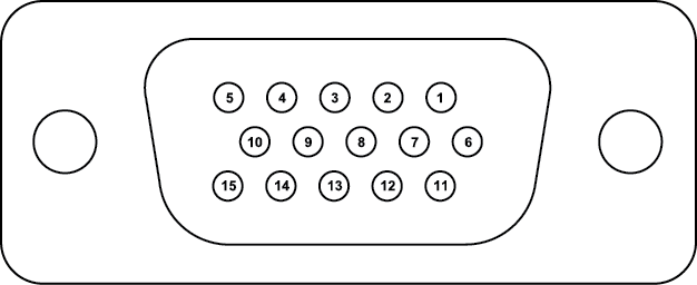
This view is of the female chassis connector on the DataPort card.
|
Pin |
Signal Description |
Description |
|---|---|---|
|
1 |
Channel 1 Minus (-) Signal |
Channel 1 Audio (-) |
|
2 |
AC Standby Control |
Places the amplifier in standby |
|
3 |
V-MON Channel 1 Subcode 1 - Bridge Mode & Power Detect |
Voltage on Channel 1 Detects bridge mode of the amplifier Detects amplifier power on |
|
4 |
I-MON Channel 1 Subcode 2 - Temperature, Channel 1 |
Current on Channel 1 Typically amplifier temperature, but may vary depending on amplifier model. |
|
5 |
Clipping Channel 1 Protect Channel 1 |
The Clipping indicator goes on immediately if channel 1 is clipping. The Protect indicator goes on if the amplifier is overheating or has an over-current condition. This condition essentially disconnects the outputs from the amplifier. |
|
6 |
Hard Ground |
Chassis ground |
|
7 |
Channel 1 Plus (+) Signal |
Channel 1 Audio (+) |
|
8 |
Channel 2 Plus (+) Signal |
Channel 2 Audio (+) |
|
9 |
+15 V from Amplifier |
Unused Input |
|
10 |
Data Reference Ground |
Reference for all monitor signals. |
|
11 |
Channel 2 Minus (-) Signal |
Channel 2 Audio (-) |
|
12 |
Amplifier IDR (Model ID) |
Each amplifier contains a resistor with a specific resistance that identifies the amplifier model The resistance is measured by the DPIO. The amplifier model is used to correctly interpret all other DPIO data and signals. If the amplifier identified in Q-SYS Designer is different from what is detected, an error is displayed. The model that is detected is used for calculations regardless of the model identified in Q-SYS Designer. |
|
13 |
V-MON Channel 2 Subcode 3 - Standby Mode Detect |
Voltage on Channel 2 When the amplifier is first powered up, it goes into standby mode prior to normal mode and is indicated on this pin. In addition, if the amplifier is placed in the standby mode it is indicated on this pin. |
|
14 |
I-MON Channel 2 Subcode 4 - Temperature, Channel 2 |
Current on Channel 2 Typically amplifier temperature, but may vary depending on amplifier model. |
|
15 |
Clipping Channel 2 Protect Channel 2 |
The Clipping indicator goes on immediately if channel 2 is clipping. The Protect indicator goes on if the amplifier is overheating or has an over-current condition. This condition essentially disconnects the outputs from the amplifier. |