GPIO Interface
The General Purpose Input Output (GPIO) interface is used to integrate Q-SYS with custom or third-party controls. The GPIO allows you to control external hardware and certain aspects of Q-SYS using external hardware.
Relay and Dry-Contact Outputs
In addition to logic-level GPIO pins, several Q SYS devices provide isolated dry-contact relay outputs for controlling external equipment that expects a simple contact closure. These relays are voltage-free contacts (NO / C / NC) and do not supply power; they are intended to switch external low-voltage control circuits (for example, screen, blind, power sequencer, or other contact closure inputs).
Dry-contact relay outputs are available on:
-
Core510i – GPIO relay pins: RNO / RNC / RC, 30 V, 1 A.
-
DCIO / DCIO-H – 4 relay outputs.
-
CX-Q, CXD-Q, DPA-Q – amplifier GPIO relay block: RELAY NO / COM /NC.
-
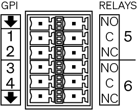
MPA-Q - amplifier 4 GPIs and 2 relay outputs on a 12-pin Euro connector: NO, C, NC per relay.
-
QIO-LVR4 – 4 relay outputs on a 12-pin Euro connector: NO, C, NC per relay.
Use these relay contacts when you need a voltage-free contact closure interface, rather than a powered or logic-level GPIO output.
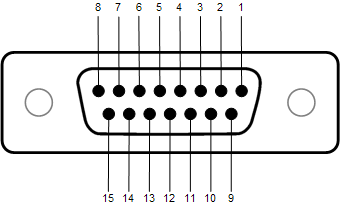
|
DB-15 Pin # |
Signal Name |
Signal Type |
Description |
|---|---|---|---|
|
1 |
RNO |
Relay Contact |
Relay Normally Open 1 |
|
2 |
RNC |
Relay Contact |
Relay Normally Closed 1 |
|
3 |
GPIO-1 |
Normal Current |
Configurable 2 |
|
4 |
GPIO-3 |
Normal Current |
Configurable |
|
5 |
Power |
Power |
+12 VDC |
|
6 |
GPIO-5 |
High Current |
Configurable |
|
7 |
GPIO-7 |
High Current |
Configurable |
|
8 |
GND |
Ground |
Ground |
|
9 |
RC |
Relay Common |
Relay Common 1 |
|
10 |
GND |
Ground |
Ground |
|
11 |
GPIO-2 |
Normal Current |
Configurable |
|
12 |
GPIO-4 |
Normal Current |
Configurable |
|
13 |
Power |
Power |
+12 VDC |
|
14 |
GPIO-6 |
High Current |
Configurable |
|
15 |
GPIO-8 |
High Current |
Configurable |
1. The GPIO Relay is controlled in a Q-SYS Design.2. When Using a Word Clock. The GPIO input impedance is much higher than what would normally be required to terminate a word clock signal. QSC recommends using a termination resistor between pin 3 and ground (pin 8 or 10). The resistor value should match the cable impedance. If the cable impedance is unknown, use 75 Ohm. Refer to the GPIO component for more information about external clocks. |
|||
| Name | Normal Current Pins | High Current Pins |
|---|---|---|
|
Maximum Input Range |
0 V to 32 V |
0 V to 32 V |
|
Analog Input Range |
0 V to 24 V |
0 V to 24 V |
|
Digital Input, Low |
0.8 V maximum |
0.8 V maximum |
|
Digital Input, High |
2.0 V minimum |
2.0 V minimum |
|
Digital Output, Low |
0.4 V maximum |
0.4 V maximum |
|
Digital Output, High |
2.4 V minimum, 3.3 V maximum |
2.4 V minimum, 3.3 V maximum |
|
Digital Output Impedance |
1 k ohm |
1 k ohm |
|
High Current Output, Low |
N / A |
0.4 V maximum |
|
High Current Output, High |
N / A |
11 V minimum, 13 V maximum |
|
High Current Output sink |
280 mA |
280 mA |
|
High Current Output source |
N / A |
280 mA |
| Specifications | ||
|---|---|---|
|
Relay Pins |
Maximum Voltage, relative to Ground |
30 V |
|
Maximum Current through Relay |
1 Amp |
|
|
Power Pins |
Output Voltage |
11 V min 13 V max |
|
Maximum Output Current |
400 mA |
|
|
All Power and High Current pins combined |
Maximum Source Current |
400 mA |
|
All GPIO Pins 1 through 8 combined |
Maximum Sink Current |
1 A using 1 GND pin 2 A using 2 GND pins |
For more information on its properties, please visit GPIO (Core 510i).
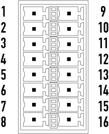
|
Connector Pin |
GPIO# and Function |
Specification |
16-pin Euro Style Connector |
|---|---|---|---|
|
1 |
3.3 V |
100 mA max (power cycle to reset current limiting IC) |
|
|
2 |
GPIO 1 |
5mA in/out, 3.3V max, 127 Ohm resistor in series |
|
|
3 |
GPIO 2 |
5mA in/out, 3.3V max, 127 Ohm resistor in series |
|
|
4 |
GND |
Ground |
|
|
5 |
GPIO 3 |
5mA in/out, 3.3V max, 127 Ohm resistor in series |
|
|
6 |
GPIO 4 |
5mA in/out, 3.3V max, 127 Ohm resistor in series |
|
|
7 |
GND |
Ground |
|
|
8 |
GPIO 5 |
18mA in/out max, 3.3V max, 127 Ohm resistor in series |
|
|
9 |
RELAY NO |
Relay Normally Open |
|
|
10 |
RELAY COM |
Relay Common |
|
|
11 |
RELAY NC |
Relay Normally Closed |
|
|
12 |
GND |
Ground |
|
|
13 |
GPIO 6 |
18mA in/out max, 3.3V max, 127 Ohm resistor in series |
|
|
14 |
GPIO 7 |
18mA in/out max, 3.3V max, 127 Ohm resistor in series |
|
|
15 |
GND |
Ground |
|
|
16 |
GPIO 8 |
18mA in/out max, 3.3V max, 127 Ohm resistor in series |
For more information on its properties, please visit GPIO (CX-Q, CXD-Q, and DPA-Q Series).
|
Connector Pin |
GPIs and Relays |
Specification |
12-pin Euro Style Connector |
|---|---|---|---|
|
|
GND |
Ground |
|
|
1 |
GPI 1 |
3.3V max, 127Ω resistor in series |
|
|
2 |
GPI 2 |
3.3V max, 127Ω resistor in series |
|
|
3 |
GPI 3 |
3.3V max, 127Ω resistor in series |
|
|
4 |
GPI 4 |
3.3V max, 127Ω resistor in series |
|
|
|
GND |
Ground |
|
|
5 |
NO |
Relay Normally Open |
|
|
C |
Relay Common |
||
|
NC |
Relay Normally Closed |
||
|
6 |
NO |
Relay Normally Open |
|
|
C |
Relay Common |
||
|
NC |
Relay Normally Closed |
For more information on its properties, please visit GPIO (MPA-Q).
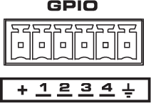
|
Connector Pin |
GPIO # and Function |
Specification |
6-pin Euro Style Connector |
|---|---|---|---|
|
|
3.3V |
100 mA max (power cycle to reset current limiting) |
|
|
1 |
GPIO 1 |
5mA in/out, 3.3V max, 127Ω resistor in series |
|
|
2 |
GPIO 2 |
5mA in/out, 3.3V max, 127Ω resistor in series |
|
|
3 |
GPIO 3 |
5mA in/out, 3.3V max, 127Ω resistor in series |
|
|
4 |
GPIO 4 |
5mA in/out, 3.3V max, 127Ω resistor in series |
|
|
|
GND |
Ground |


For more information on its properties, please visit GPIO (SPA-Qf Series).
|
Connector Pin |
GPIO # and Function |
Specification |
10-pin Euro Style Connector |
|---|---|---|---|
|
|
12V |
200 mA max (power cycle to reset current limiting) |
|
|
1 |
GPIO 1 |
5mA in/out, 3.3V max, 127Ω resistor in series |
|
|
2 |
GPIO 2 |
5mA in/out, 3.3V max, 127Ω resistor in series |
|
|
3 |
GPIO 3 |
5mA in/out, 3.3V max, 127Ω resistor in series |
|
|
4 |
GPIO 4 |
5mA in/out, 3.3V max, 127Ω resistor in series |
|
|
5 |
GPIO 5 |
5mA in/out, 3.3V max, 127Ω resistor in series |
|
|
6 |
GPIO 6 |
5mA in/out, 3.3V max, 127Ω resistor in series |
|
|
7 |
GPIO 7 |
5mA in/out, 3.3V max, 127Ω resistor in series |
|
|
8 |
GPIO 8 |
5mA in/out, 3.3V max, 127Ω resistor in series |
|
|
|
GND |
Ground |
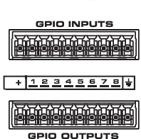
For more information on its properties, please visit GPIO In (Core 8 Flex , Core 24f, and I/O-Core 24f) and GPIO Out (Core 8 Flex , Core 24f, and I/O-Core 24f).
|
Connector Pin |
GPIO # and Function |
Specification |
10-pin Euro Style Connector |
|---|---|---|---|
|
|
12V |
200 mA max (power cycle to reset current limiting) |
|
|
1 |
GPIO 1 |
Configurable: Inputs (potentiometers) or Outputs (relays, LEDs); 3.3V Logic |
|
|
2 |
GPIO 2 |
Configurable: Inputs (potentiometers) or Outputs (relays, LEDs); 3.3V Logic |
|
|
3 |
GPIO 3 |
Configurable: Inputs (potentiometers) or Outputs (relays, LEDs); 3.3V Logic |
|
|
4 |
GPIO 4 |
Configurable: Inputs (potentiometers) or Outputs (relays, LEDs); 3.3V Logic |
|
|
5 |
GPIO 5 |
Configurable: Inputs (potentiometers) or Outputs (relays, LEDs); 3.3V Logic |
|
|
6 |
GPIO 6 |
Configurable: Inputs (potentiometers) or Outputs (relays, LEDs); 3.3V Logic |
|
|
7 |
GPIO 7 |
Configurable: Inputs (potentiometers) or Outputs (relays, LEDs); 3.3V Logic |
|
|
8 |
GPIO 8 |
Configurable: Inputs (potentiometers) or Outputs (relays, LEDs); 3.3V Logic |
|
|
|
GND |
Ground |
For more information on its properties, please visit GPIO In (Core 110f, I/O-Core 110f, Core 110c) and GPIO Out (Core 110f, I/O-Core 110f, Core 110c).
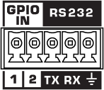
Note: The RS-232 and GPIO IN pins share a 5-pin Euro connector. You can use both connection types simultaneously.
|
Connector Pin |
GPIO # and Function |
Specification |
RS-232 5-pin Euro Connector |
|---|---|---|---|
|
1 |
GPIO 1 |
Digital Input (TTL 3.3 V) |
|
|
2 |
GPIO 2 |
Digital Input (TTL 3.3 V) |
|
|
3 |
TX |
Digital Output (TTL 3.3 V) |
|
|
4 |
RX |
Digital Output (TTL 3.3 V) |
|
|
|
GND |
Ground |
The GPIO In component represents the GPIO IN connection pins on the rear of the NV-32-H. Use one of the included 5-pin Euro connectors. For more information on its properties, please visit GPIO In (NV-32-H) and GPIO Out (NV-32-H).
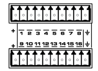
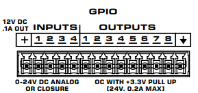
The GPIO In component represents the GPIO INPUTS connection pins on the rear of the QIO-GP8x8. Use one of the included 10-position black Euro connectors.
|
Connector Pin |
GPIO # and Function |
Specification |
10-pin Euro Style Connector |
|---|---|---|---|
|
|
12V |
200 mA max (power cycle to reset current limiting) |
|
|
1 |
GPIO 1 |
0-24 V analog input or contact |
|
|
2 |
GPIO 2 |
0-24 V analog input or contact |
|
|
3 |
GPIO 3 |
0-24 V analog input or contact |
|
|
4 |
GPIO 4 |
0-24 V analog input or contact |
|
|
5 |
GPIO 5 |
0-24 V analog input or contact |
|
|
6 |
GPIO 6 |
0-24 V analog input or contact |
|
|
7 |
GPIO 7 |
0-24 V analog input or contact |
|
|
8 |
GPIO 8 |
0-24 V analog input or contact |
|
|
|
GND |
Ground |
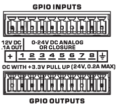
The GPIO In component represents the GPIO INPUTS connection pins on the rear of the QIO-FLEX4A. Use one of the included 14-position black Euro connectors.
|
Connector Pin |
GPIO # and Function |
Specification |
14-pin Euro Style Connector |
|---|---|---|---|
|
|
12V |
200 mA max (power cycle to reset current limiting) |
|
|
1 |
GPIO In 1 |
Input, 0-24 V analog input or contact |
|
|
2 |
GPIO In 2 |
Input, 0-24 V analog input or contact |
|
|
3 |
GPIO In 3 |
Input, 0-24 V analog input or contact |
|
|
4 |
GPIO In 4 |
Input, 0-24 V analog input or contact |
|
|
1 |
GPIO Out 1 |
Digital Output (TTL 3.3V) |
|
|
2 |
GPIO Out 2 |
Digital Output (TTL 3.3V) |
|
|
3 |
GPIO Out 3 |
Digital Output (TTL 3.3V) |
|
|
4 |
GPIO Out 4 |
Digital Output (TTL 3.3V) |
|
|
5 |
GPIO Out 5 |
Digital Output (TTL 3.3V) |
|
|
6 |
GPIO Out 6 |
Digital Output (TTL 3.3V) |
|
|
7 |
GPIO Out 7 |
Digital Output (TTL 3.3V) |
|
|
8 |
GPIO Out 8 |
Digital Output (TTL 3.3V) |
|
|
|
GND |
Ground |
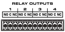
|
Connector Pin |
Description |
Specification |
12-pin, 3.5 mm Euro Connector |
|---|---|---|---|
| 1 | Relay 1 Normally Closed |
30 V AC/DC at 1A |
|
| 2 | Relay 1 Contact |
30 V AC/DC at 1 A |
|
| 3 | Relay 1 Normally Closed |
30 V AC/DC at 1 A |
|
| 4 | Relay 2 Normally Open |
30 V AC/DC at 1 A |
|
| 5 | Relay 2 Contact |
30 V AC/DC at 1 A |
|
| 6 | Relay 2 Normally Closed | 30 V AC/DC at 1 A | |
| 7 | Relay 3 Normally Open | 30 V AC/DC at 1 A | |
| 8 | Relay 3 Contact | 30 V AC/DC at 1 A | |
| 9 | Relay 3 Normally Closed | 30 V AC/DC at 1 A | |
| 10 | Relay 4 Normally Open | 30 V AC/DC at 1 A | |
| 11 | Relay 4 Contact | 30 V AC/DC at 1 A | |
| 12 | Relay 4 Normally Closed | 30 V AC/DC at 1 A |
For more information on its properties, please visit GPIO In (QIO Devices) and GPIO Out (QIO Series)