DataPort Amplifier Backup Panel (DAB-801 )
Note: The DAB-801 is discontinued. Refer to the Discontinued Products page for installation instructions and other details.
The purpose of the DataPort Amplifier Backup Panel is to provide the redundancy and other functionality required by most Life-Safety/Evacuation systems. In order to meet those requirements, the DAB-801, when used in a Q-SYS system, must be used with QSC DataPort amplifiers and Q-SYS I/O Frames with DataPort cards installed. All of the amplifiers connected to a DAB-801, or a set of stacked DAB-801s, must be the same model/channel count.
The DAB-801 is intended to mount on rear rack rails, or behind an amplifier rack.
The DAB-801 provides N+1 amplifier redundancy for QSC 2 and 4-channel DataPort amplifiers, and supports I/O Frame redundancy. Two DAB-801s can be stacked to provide double the primary amplifier redundancy.
- A single DAB-801 supports four 2-channel primary amplifiers with one 2-channel backup amplifier, or two 4-channel primary amplifiers with one 4-channel backup amplifier.
- A pair of DAB-801s support eight 2-channel primary amplifiers with one 2-channel backup amplifier, or four 4-channel primary amplifiers with one 4-channel backup amplifier.
Note: The DAB-801 does not support 8-channel amplifiers.
For complete details refer to the Amplifier Redundancy topic.
DAB-801 Connectors
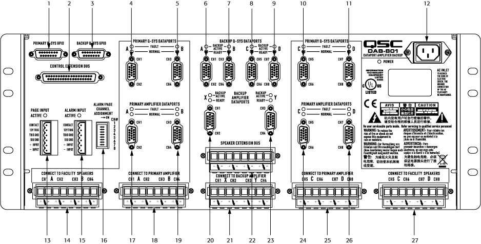
One DAB-801 can connect:
- Four 2-channel or two 4-channel primary amplifiers with one 2-channel or one 4-channel backup amplifier,
- One primary I/O Frame with 2 DataPort cards, and one backup I/O Frame with two DataPort cards,
- Eight facility loudspeakers
|
# |
Connector Name on DAB-801 |
Connector Type |
Connects To |
|---|---|---|---|
|
1 |
Primary Q-SYS GPIO |
DA-15 |
Primary Q-SYS I/O Frame GPIO |
|
2 |
Control Extension Bus |
Extension or second DAB-801 |
|
|
3 |
Backup Q-SYS GPIO |
DA-15 |
Backup Q-SYS I/O Frame GPIO |
|
4 |
Primary Q-SYS DataPorts - A - Ch1 - Ch2 |
DE-15 (Pinout) |
Primary Q-SYS I/O Frame DataPort (Ch1 - 2 1) |
|
5 |
Primary Q-SYS DataPorts - B - Ch3 - Ch4 |
DE-15 |
Primary Q-SYS I/O Frame DataPort (Ch3 - 4 1) |
|
6 |
Backup Q-SYS DataPorts - A - Ch1 - Ch2 |
DE-15 |
Backup Q-SYS I/O Frame DataPort (Ch1 - 2 1) |
|
7 |
Backup Q-SYS DataPorts - B - Ch3 - Ch4 |
DE-15 |
Backup Q-SYS I/O Frame DataPort (Ch3 - 4 1) |
|
8 |
Backup Q-SYS DataPorts - C - Ch5 - Ch6 |
DE-15 |
Backup Q-SYS I/O Frame DataPort (Ch5 - 6 1) |
|
9 |
Backup Q-SYS DataPorts - D - Ch7 - Ch8 |
DE-15 |
Backup Q-SYS I/O Frame DataPort (Ch7 - 8 1) |
|
10 |
Primary Q-SYS DataPorts - C - Ch5 - Ch6 |
DE-15 |
Primary Q-SYS I/O Frame DataPort (Ch5 - 6 1) |
|
11 |
Primary Q-SYS DataPorts - D - Ch7 - Ch8 |
DE-15 |
Primary Q-SYS I/O Frame DataPort (Ch7 - 8 1) |
|
12 |
Power |
18 Gauge IEC Power Cord |
Facility AC Power Outlet |
|
13 |
Page Input |
6-Position "Euro" or "Phoenix" type (Pinout) |
Line Level Input - See Pinout |
|
14 |
Connect to Facility Speakers - A - Ch1 - Ch2, B - Ch3 - Ch4 |
8 position high current "Euro" or "Phoenix" type |
Facility Loudspeakers 1 through 4 |
|
15 |
Alarm Input |
6-Position "Euro" or "Phoenix" type (Pinout) |
Line Level Input - See Pinout |
|
16 |
Alarm / Page Channel Assignment |
DIP Switch (Settings) |
N / A |
|
17 |
Primary Amplifier DataPorts - A - Ch1 - Ch2 |
DE-15 |
Primary Amplifier DataPort 2 Four 2-channel amplifiers - connects to amp #1, Ch1 - 2 Two 4-channel amplifiers - connects to amp #1, Ch1 - 2 |
|
18 |
Connect to Primary Amplifier A - Ch1 - Ch2 B - Ch3 - Ch4 |
8-Position high current "Euro" or "Phoenix" type |
Primary Amplifier Loudspeaker connections: Four 2-Channel Amps: (A) Amp #1 Ch1 - 2 and (B) Amp #2 Ch1 - 2 Two 4-Channel Amp: Amp #1 (A) Ch1 - 2 and (B) Ch3 - 4 |
|
19 |
Primary Amplifier DataPorts - B - Ch3 - Ch4 |
DE-15 |
Primary Amplifier DataPort 2 Four 2-channel amplifiers - connects to amp #2, Ch1 - 2 Two 4-channel amplifiers - connects to amp #1, Ch3 - 4 |
|
20 |
Backup Amplifier DataPorts - X - Ch1 - Ch2 |
DE-15 |
Backup Amplifier DataPort 2: 2-Channel Amp DataPort (Ch1 - 2) 4-Channel Amp DataPort (Ch1 - 2) |
|
21 |
Connect to Backup Amplifier - X - Ch1 - Ch2, Y - Ch3 - Ch4 |
8 position high current "Euro" or "Phoenix" type |
Backup Amplifier Loudspeaker connections 2-Channel Amp: X Ch1 - 2, Y (N / A) 4-Channel Amp: X Ch1 - 2, and Y Ch3 - 4 |
|
22 |
Speaker Extension Bus |
8 position high current "Euro" or "Phoenix" type |
Connects to the Speaker Extension Bus on the Extension DAB-801. |
|
23 |
Backup Amplifier DataPorts - Y - Ch3 - Ch4 |
DE-15 |
Backup Amplifier DataPort 2 2-Channel Amp - N / A 4-Channel Amp DataPort (Ch3 - 4) |
|
24 |
Primary Amplifier DataPorts - C - Ch1 - Ch2 |
DE-15 |
Primary Amplifier DataPort 2 Four 2-channel amplifiers - connects to amp #3, Ch1 - 2 Two 4-channel amplifiers - connects to amp #2, Ch1 - 2 |
|
25 |
Connect to Primary Amplifier - C - Ch5 - Ch6, D - Ch7 - Ch8 |
8 position high current "Euro" or "Phoenix" type |
Primary Amplifier Loudspeaker connections: Four 2-Channel Amps: (A) Amp #3 Ch1 - 2 and (B) Amp #4 Ch1 - 2 Two 4-Channel Amp: Amp #2 (A) Ch5 - 6 and (B) Ch7 - 8 |
|
26 |
Primary Amplifier DataPorts - D - Ch1 - Ch2 |
DE-15 |
Primary Amplifier DataPort 2 Four 2-channel amplifiers - connects to amp #3, Ch1 - 2 Two 4-channel amplifiers - connects to amp #2, Ch1 - 2 |
|
27 |
Connect to Facility Speakers - C - Ch5 - Ch6, D - Ch7 - Ch8 |
8 position high current "Euro" or "Phoenix" type |
Facility Loudspeakers 5 through 8 |
1. An I/O Frame can have up to four DataPort cards with two 2-channel DataPort connectors on each, for a total of 16 channels per I/O Frame. The DataPort cards can be installed in I/O Frame slots A through D, the lower lettered slot takes the lower numbered channels. Slot A has channels 1 - 4, if there was another card in slot D, it would have channels 5 - 8.2. The DataPorts on amplifiers are labeled with only "DataPort", but they are associated with the adjacent channels. |
|||
DAB-801 Indicators
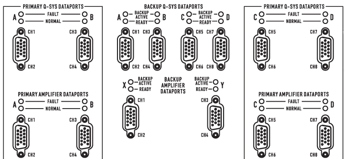
Primary DataPort Indicators
- Normal (Green) indicates that both channels associated with the DataPort connector on either the I/O Frame or Amplifier are working properly.
- Fault (Red) indicates that there is some error or failure on the associated DataPort. This could be one or both of the channels on that DataPort.
Backup DataPort Indicators
- Ready (Green) indicates that both of the channels associated with the DataPort connector are ready to be used for backup duty. It also indicates that the Backup I/O Frame or Backup Amplifier is properly connected and powered up.
- Backup (Yellow) Active indicates that one of the Primary I/O Frames or Primary Amplifiers has a fault in one or more of the channels or the entire unit, and this Backup unit has taken over for the failed unit.
Installation and Service Notes
Loudspeaker Connections
Loudspeaker wiring from the amplifiers and to the loudspeakers are connected to the DAB-801 using heavy duty, latching Euro or "Phoenix" connectors with non-loosening set screws that accept up to 10 gauge wire. Five 8-pin connectors are provided:
- Two for loudspeakers 1-4 and 5-8
- Two for Primary Amplifier Speaker Outputs 1-4 and 5-8
- One for Backup Amplifier Speaker Outputs 1-4 (for 2-ch or 4-ch use).
DataPort Connections
DataPort connections use the QSC DataPort cable, with locking DE-15 connectors for secure, stable connections. Each DataPort cable serves two amplifier channels. Each DataPort card has two DataPort connectors.
- On a single DAB-801, four DataPort connections support the primary I/O Frame with two DataPort cards installed.
- On a single DAB-801, four DataPort connections supports a backup I/O Frame with two DataPort cards installed.
- Four DataPort connections supports up to four 2-channel or two 4-channel primary amplifiers.
- Two DataPort connections supports a 2-channel or 4-channel backup amplifier. (With a 2-channel backup amplifier, the second DataPort is not used.)
Note: A QSC DataPort cable is required for connection from the DataPort card to the DataPort amplifier or DAB-801. These appear to be common VGA cables but they are not. Many off-the-shelf VGA cables MIGHT work with satisfactory results, however it is also quite possible off-the-shelf cables will give less-than-satisfactory results, and could even cause damage to QSC DataPort amplifiers! The QSC DataPort specification requires that all conductors be present, as well as shielding over those conductor pairs used for the audio channels to the amplifier. Therefore, QSC recommends the use of QSC DataPort cables exclusively, which are available in a variety of lengths from QSC. Use of any non-QSC DataPort cable may void the warranty.

GPIO Connections
The GPIO from the I/O Frame to the DAB-801 uses locking DA-15 connectors. In a stacked-DAB-801 configuration, the GPIO (from both I/O Frames) connects to the primary DAB-801 only. The control to the secondary DAB-801 is passed through the DC-37 connection between the DAB-801s.
Stacking DataPort Amplifier Backup Panels
A DC-37 connector is used to connect two DAB-801s together, passing DataPort signals and GPIO control to the secondary panel. An 8-pin Phoenix type connector is used to is used for the backup amplifier's loudspeaker connections to the second panel.
Internal logic causes the second panel to automatically number its primary amplifiers 5 thru 8, to avoid conflicts with amplifiers 1-4 connected to the first panel.
AC Power
Each panel has a locking IEC connector and requires 10 W of power, 100-250 Vac. No power switch is provided, to reduce points of failure and to prevent tampering.
LED Indicators
Although Q-SYS provides a complete fault report, to aid on-the-spot servicing, LEDs are provided that show the status of all connected equipment. Green LEDs next to each I/O and amplifier DataPort connection show if the connected device is powered up. When Q-SYS replaces a faulty device it triggers a red LED, and when a backup device is in use, it shows a yellow LED. Use of the Alarm or Page functions will trigger red LEDs next to each Page input.
Connector Pinouts
|
DB-15 Pin # |
Signal Name |
Signal Type |
Description |
|---|---|---|---|
|
1 |
RNO |
Relay Contact |
Relay Normally Open 1 |
|
2 |
RNC |
Relay Contact |
Relay Normally Closed 1 |
|
3 |
GPIO-1 |
Normal Current |
Configurable 2 |
|
4 |
GPIO-3 |
Normal Current |
Configurable |
|
5 |
Power |
Power |
+12 VDC |
|
6 |
GPIO-5 |
High Current |
Configurable |
|
7 |
GPIO-7 |
High Current |
Configurable |
|
8 |
GND |
Ground |
Ground |
|
9 |
RC |
Relay Common |
Relay Common 1 |
|
10 |
GND |
Ground |
Ground |
|
11 |
GPIO-2 |
Normal Current |
Configurable |
|
12 |
GPIO-4 |
Normal Current |
Configurable |
|
13 |
Power |
Power |
+12 VDC |
|
14 |
GPIO-6 |
High Current |
Configurable |
|
15 |
GPIO-8 |
High Current |
Configurable |
1. The GPIO Relay is controlled in a Q-SYS Design.2. When Using a Word Clock. The GPIO input impedance is much higher than what would normally be required to terminate a word clock signal. QSC recommends using a termination resistor between pin 3 and ground (pin 8 or 10). The resistor value should match the cable impedance. If the cable impedance is unknown, use 75 Ohm. Refer to the GPIO component for more information about external clocks. |
|||
| Name | Normal Current Pins | High Current Pins |
|---|---|---|
|
Maximum Input Range |
0 V to 32 V |
0 V to 32 V |
|
Analog Input Range |
0 V to 24 V |
0 V to 24 V |
|
Digital Input, Low |
0.8 V maximum |
0.8 V maximum |
|
Digital Input, High |
2.0 V minimum |
2.0 V minimum |
|
Digital Output, Low |
0.4 V maximum |
0.4 V maximum |
|
Digital Output, High |
2.4 V minimum, 3.3 V maximum |
2.4 V minimum, 3.3 V maximum |
|
Digital Output Impedance |
1 k ohm |
1 k ohm |
|
High Current Output, Low |
N / A |
0.4 V maximum |
|
High Current Output, High |
N / A |
11 V minimum, 13 V maximum |
|
High Current Output sink |
280 mA |
280 mA |
|
High Current Output source |
N / A |
280 mA |
| Specifications | ||
|---|---|---|
|
Relay Pins |
Maximum Voltage, relative to Ground |
30 V |
|
Maximum Current through Relay |
1 Amp |
|
|
Power Pins |
Output Voltage |
11 V min 13 V max |
|
Maximum Output Current |
400 mA |
|
|
All Power and High Current pins combined |
Maximum Source Current |
400 mA |
|
All GPIO Pins 1 through 8 combined |
Maximum Sink Current |
1 A using 1 GND pin 2 A using 2 GND pins |
For more information on its properties, please visit GPIO (Core 510i).
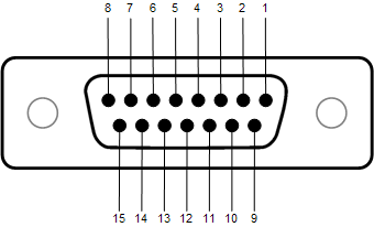
DataPort DE-15 Connector Pinout
The illustration below shows the pin assignments used for the DataPort DE-15 (female 15-pin high-density D shell) connectors.
This information is shown for reference only and is subject to change without notice as the DataPort feature is specific to QSC products and not intended for interface to other manufacturer's equipment.
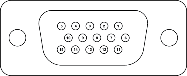
This view is of the female chassis connector on the DataPort card.
|
Pin |
Signal Description |
Description |
|---|---|---|
|
1 |
Channel 1 Minus (-) Signal |
Channel 1 Audio (-) |
|
2 |
AC Standby Control |
Places the amplifier in standby |
|
3 |
V-MON Channel 1 Subcode 1 - Bridge Mode & Power Detect |
Voltage on Channel 1 Detects bridge mode of the amplifier Detects amplifier power on |
|
4 |
I-MON Channel 1 Subcode 2 - Temperature, Channel 1 |
Current on Channel 1 Typically amplifier temperature, but may vary depending on amplifier model. |
|
5 |
Clipping Channel 1 Protect Channel 1 |
The Clipping indicator goes on immediately if channel 1 is clipping. The Protect indicator goes on if the amplifier is overheating or has an over-current condition. This condition essentially disconnects the outputs from the amplifier. |
|
6 |
Hard Ground |
Chassis ground |
|
7 |
Channel 1 Plus (+) Signal |
Channel 1 Audio (+) |
|
8 |
Channel 2 Plus (+) Signal |
Channel 2 Audio (+) |
|
9 |
+15 V from Amplifier |
Unused Input |
|
10 |
Data Reference Ground |
Reference for all monitor signals. |
|
11 |
Channel 2 Minus (-) Signal |
Channel 2 Audio (-) |
|
12 |
Amplifier IDR (Model ID) |
Each amplifier contains a resistor with a specific resistance that identifies the amplifier model The resistance is measured by the DPIO. The amplifier model is used to correctly interpret all other DPIO data and signals. If the amplifier identified in Q-SYS Designer is different from what is detected, an error is displayed. The model that is detected is used for calculations regardless of the model identified in Q-SYS Designer. |
|
13 |
V-MON Channel 2 Subcode 3 - Standby Mode Detect |
Voltage on Channel 2 When the amplifier is first powered up, it goes into standby mode prior to normal mode and is indicated on this pin. In addition, if the amplifier is placed in the standby mode it is indicated on this pin. |
|
14 |
I-MON Channel 2 Subcode 4 - Temperature, Channel 2 |
Current on Channel 2 Typically amplifier temperature, but may vary depending on amplifier model. |
|
15 |
Clipping Channel 2 Protect Channel 2 |
The Clipping indicator goes on immediately if channel 2 is clipping. The Protect indicator goes on if the amplifier is overheating or has an over-current condition. This condition essentially disconnects the outputs from the amplifier. |
Alarm/Page Input Connector Pinout

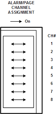
Alarm/Page Channel Assignment DIP Switch
Turning a switch to the On position indicates that if there is an alarm or page announcement, that channel is disconnected from the standard input and connected to the Alarm/Page input. The remaining channels have the option of being muted via settings for the DAB-801 component in Q-SYS Designer.