Parametric Equalizer
The Parametric Equalizer is a variable equalizer allowing you to individually adjust the Gain, Bandwidth and center Frequency of up to 32 frequency bands. You can also Bypass individual bands. Master controls, affecting all bands, include Bypass, Invert, Mute and Gain. Additionally, you can change any or all of the bands to either a high or low-shelf equalizer, allowing you to vary the gain of all frequencies, as a group, above or below a selected frequency. At the selected Frequency, the gain changes approximately +3dB or -3dB depending on wether the shelf is adding or reducing gain.
Note: The number of signal pins is variable and set in the component's Type Property.
Input Pins
Channels
Audio signal pins are represented by a ( ) circle, and traditional wiring is represented by a thin black line. You can use Signal Names on audio signal pins.
By default, the Parametric Equalizer component is set to a Mono channel, which provides one input and one output. Additionally, you can set the Properties to allow for Stereo, which gives you two inputs and outputs; or you can choose Multi-Channel, which will allow you to choose between 2 and 256 inputs and outputs.
Output Pins
Channels
Audio signal pins are represented by a () circle, and traditional wiring is represented by a thin black line. You can use Signal Names on audio signal pins.
By default, the Parametric Equalizer component is set to a Mono channel, which provides one input and one output. Additionally, you can set the Properties to allow for Stereo, which gives you two inputs and outputs; or you can choose Multi-Channel, which will allow you to choose between 2 and 256 inputs and outputs.
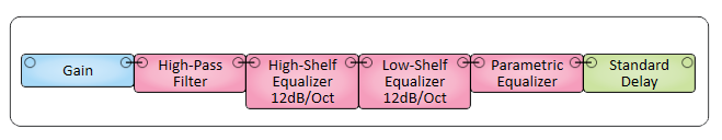
In this example, we have all of our audio channels routed through a series of Equalizers and Filters before being delivered to our Amplifiers. The Parametric Equalizer is where most of the equalization takes place.
Tip: For additional properties that are not listed, refer to the Properties Panel help topic for more information.
Parametric Equalizer Properties
Band Count
Sets the number of bands available in the Equalizer, from 1 to 32.
Bandwidth or Q-Factor
Select whether to display Bandwidth, Q-Factor, or both controls in the control panel.
High Precision
Select Yes to expand the frequency display precision to show tenths of Hz below 1 kHz and whole Hz above 1 kHz. The default is No.
Channels
Type
Sets the type of Channel available for Inputs and Outputs.
Count
Only appears when choosing Multi-Channel as the Type. Sets the number of Channels for Multi-channel. You can choose between 2 and 256.
Response Panel
Enabled
Enables or disables the graphical Response graph.
Size
Sets the size of the graphical Response graph.
Response Panel
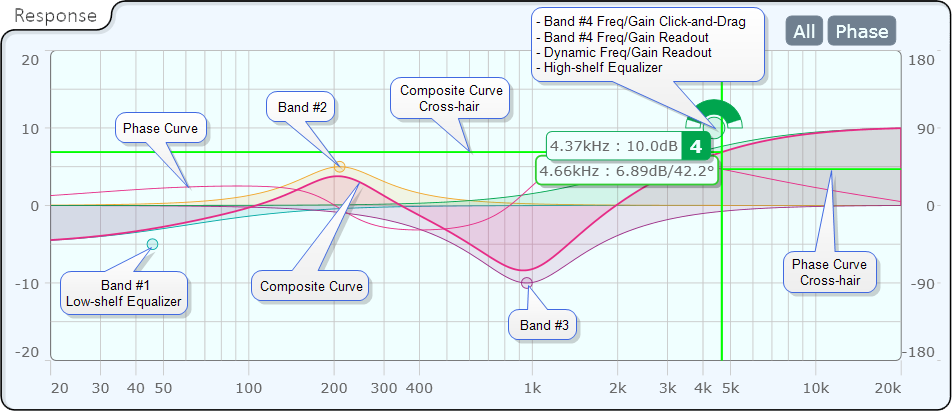
The Response panel provides vertical and horizontal cross-hairs with a dynamic frequency and level read-out. Place the mouse courser over the graph to activate the cross-hairs. When the Phase control is activated, the horizontal cross-hair line to the left of center represents the normal curve, the right side represents the phase curve. The readout is only for the normal curve.
All (Bands)
A toggle button that activates a graphical display all bands of the equalizer. When the button is not enabled, the Response Panel displays a composite of all the bands. The composite cannot be turned off.
Phase
Turns the Phase curve display on and off.
Bypass
Bypasses the equalizer.
Invert
Inverts the output signal of the equalizer.
Mute
Mutes the output of the equalizer.
Gain (dB)
Sets the overall gain of the equalizer.
Bypass
Bypasses an individual frequency band.
Gain (dB)
Controls the gain for an individual frequency band.
Bandwidth (Octave)
If enabled in Properties, sets the bandwidth of an individual band of the equalizer, from .010 octaves to
Q-Factor
If enabled in Properties, sets the Q-factor of an individual band of the equalizer. This is not active when either Low-shelf or High-shelf Type is selected. Adjusting Q-Factor generally adjusts Bandwidth in an inverse manner.
Frequency (Hz)
Sets the center Frequency of an individual band.
Type
Selects the type of equalizer for that band.
|
Pin Name |
Value |
String |
Position |
Pins Available |
|---|---|---|---|---|
|
(band) Bandwidth |
.010 to 1.00 |
.010 to 1.00 |
0.000 to 1.00 |
Input / Output |
|
(band) Bypass |
0 1 |
active bypass |
0 1 |
Input / Output |
|
(band) Equalizer Type |
1 2 3 |
Parametric Low-shelf High-shelf |
0 0.5 1.00 |
Input / Output |
|
(band) Frequency |
10 to 20000 |
10 Hz to 20 kHz |
0.000 to 1.00 |
|
|
(band) Gain |
-18 to 18 |
-18 dB to 18 dB |
0.000 to 1.00 |
Input / Output |
|
Master Bypass |
0 1 |
active bypass |
0 1 |
Input / Output |
|
Master Gain |
-20 to 20 |
-20 dB to 20 dB |
0.000 to 1.00 |
Input / Output |
|
Master Invert |
0 1 |
normal invert |
0 1 |
Input / Output |
|
Master Mute |
0 1 |
unmute mute |
0 1 |
Input / Output |