GPIO (DCIO/DCIO-H)
This topic describes how to configure and control the General Purpose Input Output (GPIO) hardware interface using Q-SYS Designer for the DCIO and DCIO-H.
The General Purpose Input Output (GPIO) Controller is used to integrate Q-SYS with custom or third-party controls. Using the GPIO you can control external hardware and certain aspects of Q-SYS using external hardware.
The GPIO Interface is physical hardware, and is represented in Q-SYS Designer by the GPIO component. There is one GPIO component available in each DCIO / DCIO-H component added to the Inventory. There are six GPI pins representing the Automation Inputs RJ-45 and four GPO Relay pins representing the two six-position Euro-style connectors. In addition, there is a Level Knob and a Mute Button, each having input and output control pins. These controls are connected to the Mute and Level controls on the front panel of the DCIO. Refer to the Properties section in this topic for details.
The GPIO control pins on the GPIO component can be displayed (used) or not displayed (not used) by settings in the Properties.
Tip: For additional properties that are not listed, refer to the Properties Panel help topic for more information.
DCIO Properties
Use Frontpanel
Controls the display of the Mute button and the Level knob in the GPIO control panel.
Use Relays
Controls the display of Relay buttons in the GPIO control panel.
Use GPIO
Controls the display of the Mute button and the Level knob in the GPIO control panel.
GPIO Input Type
Selects the type of GPIO Input. You can choose between Contact Closure Input and Digital Input (TTL 3.3V).
The numbered Controls are displayed in Relay (1 thru 4) and GPIO (1 thru 6) pin-number order. The numbers are the physical pin numbers.
General
Mute (Frontpanel)
This Mute button mutes the main output; it functions the same as the Mute button on the front panel.
Level (Frontpanel) (dB)
This Level knob controls the level of the main output; it functions the same as the Level knob on the front panel.
Relay Outputs (1-4)
|
The function of the Relay button is to open and close the contacts of the relay on the GPIO Interface. NC – Relay 1 (3) Normally Closed Pin 1 NO – Relay 1 (3) Normally Open Pin 2 C – Relay 1 (3) Common Pin 3
NC – Relay 2 (4) Normally Closed Pin 4 NO – Relay 2 (4) Normally Open Pin 5 C – Relay 2 (4) Common Pin 6
|
Rear Panel 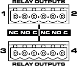

|
GPIO Inputs (1-6)
There are 6 GPInputs. The green LED illuminates when there is a digital high on the associated pin. The following list is describing the input connector on the rear panel.
| Automation Inputs (RJ-45) | |
|---|---|
| Pin # | Description |
|
1 |
GPI 1 |
|
2 |
GPI 2 |
|
3 |
GPI 3 |
|
4 |
GPI 4 |
|
5 |
GPI 5 |
|
6 |
GPI 6 |
|
7 |
Unused |
|
8 |
Ground |
The GPIO component has no Control Pins.