IR Receiver
Use the IR Receiver component to learn commands sent from the IR Input (QIO-IR1x4) component. Received commands can be saved, labeled, and optionally sent to the IR Output (QIO-IR1x4) component. Commands are saved locally within the IR Receiver component within the design.
Tip: Commands can also be received from an IR Driver component for the purpose of saving and relabeling commands from the IR command database.
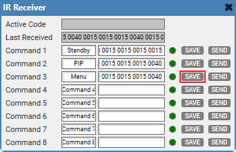
- From the Schematic Elements > Components > Control Components category, drag an IR Receiver component into your design.
- From the Properties pane, select how many IR Sources from which to receive commands. You can optionally allow the component to send the commands you save with the Enable Transmit property. See Properties.
- Wire the component:
- Wire an IR Source pin to an IR Input Out pin on the QIO-IR1x4 IR Input component or the IR Driver Out pin on the IR Driver component.
- If you toggled the Enable Transmit property to 'Yes', wire the IR Receiver Out pin to a QIO-IR1x4 IR Output component.
- Run (F5) or emulate (F6) the design.
- Double-click the IR Receiver component to open the control panel.
- Send an IR command.
- As you send the command, the Active Code text box will populate with the command code from the device.
- After the command is sent, the Last Received control shows the command code that you can now save to any of the numbered Command assignments.
- Click within a Command Label text box to assign a label to the command.
- Click Save. The command code populates the Command text box.
- (Optional) If you set the Enable Transmit property to 'Yes', you can also click Send to send the command to an IR Output component.
Input Pins
 IR Source n
Connect this pin to the IR Input Out pin of the IR Input (QIO-IR1x4) component or the IR Driver Out pin of the IR Driver component. You can wire multiple IR sources to the component by adjusting the IR Source Count property. See Properties.
Output Pins
IR Receiver Out 
This pin is only available if the Enable Transmit property is enabled. Connect this pin to the IR Source pin of the IR Output (QIO-IR1x4) component. You can connect this pin to multiple IR components (fan-out).
These examples demonstrate some use cases for all four IR-related components in Q-SYS Designer Software:
- IR Driver and IR Receiver, which are located within the Schematic Elements > Components > Control Components category
- IR Input and IR Output, which are located within the QIO-IR1x4's Inventory tree.
Sending IR Commands
In this example, an IR Driver sends commands for a TV device to a single TV (or perhaps multiple TVs of the same model) in the same room.

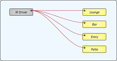
In this example, an IR Driver sends commands for a TV device to each of the four IR Outputs of the IR1x4. An emitter is placed in each room, and each room has the same model TV. This example shows a hypothetical setup for a restaurant that contains four spaces with entertainment.
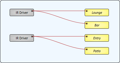
This example is similar to Example 2, except that two rooms have TVs of one model and the other two rooms use a different model. Therefore, two IR Drivers are required.
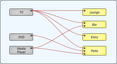
This example demonstrates how multiple IR Drivers - each for a different IR device - can be sent to multiple IR Outputs, with some IR Outputs sending IR commands from multiple sources. Each room has an IR emitter connected to an IR Output of the QIO-IR1x4.
- The Lounge and Entry only contain a TV.
- The Bar contains both a TV and a Media Player. Its IR Source Count property is set to '2'.
- The Patio has a TV, DVD player, and Media Player. Its IR Source Count property is set to '3'.
Note: For those IR Outputs sending commands from multiple sources (Bar and Patio), only a single IR command can be sent at a time.
Receiving IR Commands
In this example, the QIO-IR1x4's IR Input receives IR commands from an IR device – for example, a remote control for a TV that is not in the IR Driver's database. Each command can then be saved and labeled in the IR Receiver component.
Tip: Commands are saved locally within the IR Receiver component within the design.

In this example, an IR Receiver can learn commands from two QIO-IR1x4 devices. The IR Receiver's IR Source Count property is set to '2'.
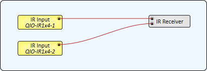
Similar to Example 5, an IR Receiver learns commands from a QIO-IR1x4's IR Input. However, those learned commands can then be sent to one or more IR Outputs. In this example, the IR Receiver's Enable Transmit property is set to 'Yes'.

In this example, an IR Receiver receives commands from an IR Driver. This is useful for relabeling commands from the IR Driver's database when a different description is desired.

Relaying IR Commands
In this example, a QIO-IR1x4's IR Input is wired directly to its IR Outputs. This would be useful if you have an IR receiving device in one area but you want to control IR devices in other areas that are out of view of the receiver. The QIO-IR1x4 will simply relay the received commands to its outputs.
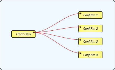
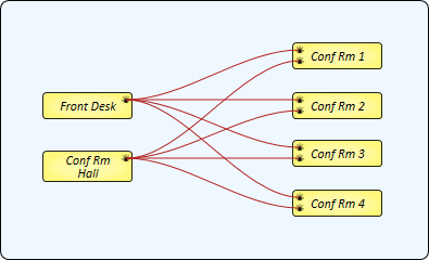
This example is the same as Example 9, except that the Conference Room devices can be controlled from two locations. "Front Desk" represents the IR Input on one QIO-IR1x4 device, while "Conf Rm Hall" is the IR Input on another QIO-IR1x4.
IR Receiver Properties
Tip: For additional properties that are not listed, refer to the Properties Panel help topic for more information.
Number of Commands
Specify how many Command controls are available within the component, from 1 to 256 (default is 8).
Commands per Page
Specify how many Command controls appear on each page/tab: 8, 16, 24, 32 (default), 64, 128, or 256. This property has no effect if the Number of Commands property is less than Commands per Page.
IR Source Count
Specify how many IR Source pins are available for upstream IR connections, from 1 to 50 (default is 1).
Show Command Labels
Select whether to display Command Label controls in the control panel. The default is 'Yes'.
Enable Transmit
Select whether to enable IR Receiver Out pins for connections to downstream IR components, as well as a Send control within the control panel.
Active Code
This is the IR code currently being received.
Last Received
This is the IR code that was last received and available to be saved.
Command n Label
If enabled in Properties, use this control to give a custom name to the last received command before or after saving it.
Command n Command
This is the IR command code of the saved command.
Command n Active LED
This LED turns on if the saved command matches the command actively being received.
Command n Save
Click to save the Last Received command.
Command n Send
If Enable Transmit is toggled on in Properties, you can optionally send a saved command.
| Pin Name | Value | String | Position | Pins Available |
|---|---|---|---|---|
|
Command n |
||||
|
Active LED |
0 1 |
false true |
0 1 |
Output |
|
Command n Command |
(text) |
Input / Output |
||
|
Command n Label |
(text) |
Input / Output |
||
|
Command n Save |
(trigger) |
Input / Output |
||
|
Command n Send |
0 1 |
false true |
0 1 |
Input / Output |
|
Active Code |
(text) |
Output |
||
|
Last Received |
(text) |
Output |
||
