PA Router
The PA Router is the hub of the Q-SYS Paging System. It performs the following tasks:
- Routes pages.
- Delays, queues and sorts delayed pages based on priority and zone availability.
- Plays and routes prerecorded messages.
- Queues and sorts message playback based on priority and zone availability.
- Mixes pages and messages with background music (BGM), including ducking.
- Routes BGM.
- Controls the Gain and Mute for Pages, Messages, and BGM.
The PA Router accepts audio files for preambles, messages and BGM. One track is supported (additional tracks are ignored). The files can be loaded onto the Core using the Q-SYS Core Manager > Files page.
The files for preambles and messages are selected in the Q-SYS Administrator > Commands tab. The files for BGM are selected in the Q-SYS Designer Schematic.
Refer to the Core-to-Core Paging topic for details.
By default, the PA Router components is set to 8 Stations and 8 Zones, providing 8 inputs and 8 outputs. You can adjust the default settings to the following, 1 to 256 stations and 1 to 512 zones using the Station Count and Zone Count properties.
Input Pins
Station Audio - Provides one audio input for each Page Station. The audio can come from any audio source available in Q-SYS Designer, such as the built-in microphone, the AUX input on the physical Page Station, the mic input on a TSC (in paging mode), an audio player, or Mic/Line input card.
Station Control - Represented by a down-pointing  triangle.
Note: Each station's Audio and Control pins are grouped together, with the groups arranged in station order.
Background Music (BGM) - Connect your background music source here. The number of available inputs is defined in PA Router Properties, BGM Input Count.
Output Pins
Zone Audio - This is an output type, represented by a ( ) circle. Provides one output for each Page Zone, as defined in PA Router Properties, Zone Count.
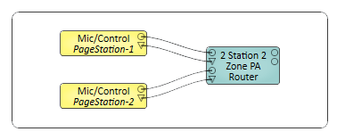
Note: To set up a Paging System, you must have at least one Page Station and only one PA Router in your design. The design will not compile if more than one PA Router is included.
In this example, we have two microphones from two Page Stations feeding into a PA Router.
Tip: For additional properties that are not listed, refer to the Properties Panel help topic for more information.
PA Router Properties
Station Count
Sets the number of Page Stations you have in your Q-SYS Design. The Page Stations can be the Virtual Page Station or the hardware proxy. The number of stations you define is available for configuration in the Administrator.
Zone Count
Sets the number of PA Zones for your paging system.
The number of Zones you define, is available in the PA Router Control Panel where you can select the BGM for each Zone.
The number of Zones is also available for configuration in the Administrator.
BGM Input Per Zone
Sets a single BGM input assigned for each PA Zone.
BGM Input Count
Sets the number of BGM inputs you want for your paging system. You can assign any one of the BGM inputs to one or more PA Zones.
Note: This setting is only available when BGM Input Per Zone is set to No.
BGM Selector Controls
Sets the selector type for choosing the BGM input source per zone.
Remote Sources Count
Sets the number of external PA Router sources to the current Core PA Router.
Remote Destination Count
This value sets the number of outputs the current Core PA Router can send to other external PA Routers and defines the number of Remote Destination Tags available for Core-to-Core paging. Each Remote Destination corresponds to a group of Remote Destination Tags configured in Q-SYS Administrator. Setting this property to a non-zero value enables the use of Remote Zone Groups in Virtual Page Station and PS-TSCG3 Mic / Control components. These groups appear as buttons in the user interface and allow direct paging to remote zones across multiple Q-SYS Cores.
Tip: Ensure that Remote Destination Tags are configured in Q-SYS Administrator and that the names match across Cores. This property must be set before Remote Zone Groups buttons will appear in the Page Station UI.
Note: Traditional Zone Tags are used to group local PA Zones within a single Q-SYS Core. These Zone Tags simplify paging by allowing commands to target multiple zones using a shared tag. However, Remote Destination Tags are used for paging across multiple Q-SYS Cores. These tags are configured in Q-SYS Administrator and linked to Remote Destinations in the PA Router. Each Remote Destination Tag can represent a group of zones on a remote Core, enabling cross-core paging from a single-button press.
For more information, see the Configuring Remote Zone Groups with Remote Destination Tags—Single-Button Press Paging for a Group of Zones section on the Core-to-Core Pagingpage.
Remote Source
Name
Sets the name for the assigned Remote Source
Type
Sets whether the assigned source is via a patched audio path, or Q-LAN stream.
Channel Count
Sets the number of audio channels for the assigned source.
Q-LAN Redundant
Enable this property if the Q-SYS Core is connected to both LAN A and LAN B for network redundancy.
Note: For the Q-SYS Core 110f and 110c, each Q-LAN Receiver with this property enabled consumes two streams instead of one. Use File > Check Design to see your design's Network Audio Input count.
Q-LAN Verbose
This property currently has no effect.
Remote Destination
Name
Sets the name for the assigned Remote Destination
Type
Sets whether the assigned destination is via a patched audio path, or Q-LAN stream.
Channel Count
Sets the number of audio channels for the assigned destination.
Q-LAN Redundant
Enable this property if the Q-SYS Core is connected to both LAN A and LAN B for network redundancy.
Note: For the Q-SYS Core 110f and 110c, each Q-LAN Receiver with this property enabled consumes two streams instead of one. Use File > Check Design to see your design's Network Audio Input count.
Q-LAN Verbose
This property currently has no effect.
Zone 1 - n
A vertical listing of all the Zones based on the Zone Count in the Properties. Can be up to 256 Zones
Name
The name as specified in PA Zones (Administrator).
Mute
Mutes all signals to the Zone. One Mute button for each Zone.
Gain (dB)
Sets the gain for all signals to the Zone. You can enter the value using your keyboard, or change it by selecting the field and dragging the mouse.
Squelch Priority
Allows you to silence pages and messages at and below the Priority level selected.
You can create a Control Command and Schedule it to change the Squelch Priority to prevent pages and messages from being played in certain zones at certain times.
Buffer
Displays the amount of PA Router audio RAM in use.
Note: You may notice the PA Router buffer percentage increases each time a new message is sent to be played. This behavior is expected. There is one hour of buffering allocated in 1 second increments available for delayed pages, messages, and preambles. Pages are discarded immediately after playback (and optionally archived). Messages and preambles will remain cached in buffers in case they are played again, but they will be discarded on a last used basis when more space is needed.
Squelch
LED indicating that the associated PA Zone is being squelched.
Active
LED indicating that the PA Zone associated with the LED is Active (illuminated) or not.
Source
A number indicating the PA Router Input Pin to which the source of the page is connected.
Priority
Text field giving the Priority of the current event.
Cancel All
Cancels all executing and queued commands.
Cancel Queued
Cancels all queued commands.
Mute
Mutes the Page output for the associated PA Zone.
Gain (dB)
Sets the gain for the Page signals to the Zone.
You can enter the value using your keyboard, or change it by selecting the field and dragging the mouse.
Mute
Mutes the Message input. One Mute button for each PA Zone.
Gain
Controls the Gain of the Message. One Gain control for each PA Zone. This Gain is in addition to the Gain set in the Output section of the associated Zone.
You can enter the value using your keyboard, or change it by selecting the field and dragging the mouse.
Message
Text field displaying the name of the Message file currently playing.
Note: These controls only appear if BGM Input Per Zone is set to Yes.
Mute (Zone)
Mutes only the BGM signal to the PA Zone. One Mute button for each Zone.
Gain (dB)
Adjusts only the BGM Gain for a single PA Zone. One Gain control for each PA Zone. This Gain is in addition to the Gain set in the Output section of the associated Zone.
You can enter the value using your keyboard, or change it by selecting the field and dragging the mouse.
Select
Displays the number of the BGM Input button you have selected for the associated Zone. In addition, you can select the Select field, and type the number corresponding to the BGM Input you wish to select.
BGM input buttons 0 - n
Radio button for each BGM Input defined in the BGM Input Count in the Properties. The buttons are numbered 1 - n, and the number of the one you select displays in the Select field. A set of buttons (1 - n) is available for each Zone.
When you select a button, the audio source connected to that BGM Input is routed to the associated Zone.
BGM Input Gain (dB)n
Adjusts the BGM Input Gain for all PA Zones associated with that BGM Input. One Gain control for each BGM Input.
BGM Ducker Attack (seconds)
The Attack is the time it takes the BGM to fall to 63% of the Depth level when the a Page or Message is played.
Use this control to provide a smooth transition from the BGM audio to the Page or Message audio.
BGM Ducker Depth (dB)
The Depth sets the amount of gain applied to the BGM Input channels when the BGM Ducker is activated. The Page or Message is mixed with the BGM, so the Depth setting controls how much of the BGM is heard in the output. Setting the Depth to 60 dB of attenuation essentially mutes all BGM channels used by the Page or Message.
BGM Ducker Release (seconds)
The Release Time is the time it takes the BGM channel outputs to return to 63% of their normal level when the BGM Ducker is deactivated - the Page or Message ends.
Use this control to provide a smooth transition from the Page or Message audio back to the BGM channel audio.
Note: Remote Source tab only appears in the Controls when Remote Sources Count is set to a non-zero number and the Type property of the Source is set to Q-LAN.
Communication Status
Component status is conveyed with the Status LED and Status box, which uses both color and text to indicate the current condition:
- OK: The device is functioning normally.
- Initializing: The device is in the process of a firmware, patch, or configuration update, or the design is starting.
- Compromised: The device is functioning, but a non-fatal problem exists. Refer to the Status box for details.
- Missing: The device cannot be discovered.
- Fault: The device is malfunctioning or is not properly configured. Refer to the Status box for details.
- Unknown: This status appears during a Core reboot (for example, during a firmware update), or when a design is being uploaded to the Core and before it has started running.
- Not Present: If applicable to the device, this status appears when the device is not connected to the network and its Is Required component property is set to 'No'. This status also appears if the device component's Dynamically Paired property is set to 'Yes', pairing has not been assigned in Core Manager, and the device component's Is Required property is set to 'Yes'. See Dynamic Pairing.
Q-LAN
Peak Output Level (dBFS)
Meters for each channel indicating the peak input level.
Digital
Invert
Toggle button to invert the digital output of the Q-LAN Receiver.
Mute
Mutes the output signal.
Gain (dB)
Controls the Gain of the digital output signal.
Status
Component status is conveyed with the Status LED and Status box, which uses both color and text to indicate the current condition:
- OK: The device is functioning normally.
- Initializing: The device is in the process of a firmware, patch, or configuration update, or the design is starting.
- Compromised: The device is functioning, but a non-fatal problem exists. Refer to the Status box for details.
- Missing: The device cannot be discovered.
- Fault: The device is malfunctioning or is not properly configured. Refer to the Status box for details.
- Unknown: This status appears during a Core reboot (for example, during a firmware update), or when a design is being uploaded to the Core and before it has started running.
- Not Present: If applicable to the device, this status appears when the device is not connected to the network and its Is Required component property is set to 'No'. This status also appears if the device component's Dynamically Paired property is set to 'Yes', pairing has not been assigned in Core Manager, and the device component's Is Required property is set to 'Yes'. See Dynamic Pairing.
Connection
Stream Name
The Stream Name identifies the connection between a Q‑LAN Transmitter, and a Q‑LAN Receiver. They must have the same Stream Name.
You can leave the Q‑LAN Receiver or Transmitter at the default setting, but at least one must be set to Dynamic Stream Name = yes in the Properties then rename the stream to match the other.
Primary OK
This LED indicates if the Primary Stream is OK or not.
Note: Remote Destination tab only appears in the Controls when Remote Sources Count is set to a non-zero number and the Type property of the Destinationis set to Q-LAN.
Zone 9 - n
A vertical listing of all the Zones based on the Remote Destination Count in the Properties. Can be up to 32 Zones
Mute
Mutes all signals to the Zone. One Mute button for each Zone.
Gain (dB)
Sets the gain for all signals to the Zone. You can enter the value using your keyboard, or change it by selecting the field and dragging the mouse.
Squelch Priority
Allows you to silence pages and messages at and below the Priority level selected.
You can create a Control Command and Schedule it to change the Squelch Priority to prevent pages and messages from being played in certain zones at certain times.
Buffer
Displays the amount of PA Router audio RAM in use.
Note: You may notice the PA Router buffer percentage increases each time a new message is sent to be played. This behavior is expected. There is one hour of buffering allocated in 1 second increments available for delayed pages, messages, and preambles. Pages are discarded immediately after playback (and optionally archived). Messages and preambles will remain cached in buffers in case they are played again, but they will be discarded on a last used basis when more space is needed.
Squelch
LED indicating that the associated PA Zone is being squelched.
Active
LED indicating that the PA Zone associated with the LED is Active (illuminated) or not.
Source
A number indicating the PA Router Input Pin to which the source of the page is connected.
Priority
Text field giving the Priority of the current event.
Cancel All
Cancels all executing and queued commands.
Cancel Queued
Cancels all queued commands.
Mute
Mutes the Page output for the associated PA Zone.
Gain (dB)
Sets the gain for the Page signals to the Zone.
You can enter the value using your keyboard, or change it by selecting the field and dragging the mouse.
Mute
Mutes the Message input. One Mute button for each PA Zone.
Gain
Controls the Gain of the Message. One Gain control for each PA Zone. This Gain is in addition to the Gain set in the Output section of the associated Zone.
You can enter the value using your keyboard, or change it by selecting the field and dragging the mouse.
Message
Text field displaying the name of the Message file currently playing.
Note: These controls only appear if BGM Input Per Zone is set to Yes.
Mute (Zone)
Mutes only the BGM signal to the PA Zone. One Mute button for each Zone.
Gain (dB)
Adjusts only the BGM Gain for a single PA Zone. One Gain control for each PA Zone. This Gain is in addition to the Gain set in the Output section of the associated Zone.
You can enter the value using your keyboard, or change it by selecting the field and dragging the mouse.
Select
Displays the number of the BGM Input button you have selected for the associated Zone. In addition, you can select the Select field, and type the number corresponding to the BGM Input you wish to select.
BGM input buttons 0 - n
Radio button for each BGM Input defined in the BGM Input Count in the Properties. The buttons are numbered 1 - n, and the number of the one you select displays in the Select field. A set of buttons (1 - n) is available for each Zone.
When you select a button, the audio source connected to that BGM Input is routed to the associated Zone.
BGM Input Gain (dB)n
Adjusts the BGM Input Gain for all PA Zones associated with that BGM Input. One Gain control for each BGM Input.
BGM Ducker Attack (seconds)
The Attack is the time it takes the BGM to fall to 63% of the Depth level when the a Page or Message is played.
Use this control to provide a smooth transition from the BGM audio to the Page or Message audio.
BGM Ducker Depth (dB)
The Depth sets the amount of gain applied to the BGM Input channels when the BGM Ducker is activated. The Page or Message is mixed with the BGM, so the Depth setting controls how much of the BGM is heard in the output. Setting the Depth to 60 dB of attenuation essentially mutes all BGM channels used by the Page or Message.
BGM Ducker Release (seconds)
The Release Time is the time it takes the BGM channel outputs to return to 63% of their normal level when the BGM Ducker is deactivated - the Page or Message ends.
Use this control to provide a smooth transition from the Page or Message audio back to the BGM channel audio.
Communication Status
Component status is conveyed with the Status LED and Status box, which uses both color and text to indicate the current condition:
- OK: The device is functioning normally.
- Initializing: The device is in the process of a firmware, patch, or configuration update, or the design is starting.
- Compromised: The device is functioning, but a non-fatal problem exists. Refer to the Status box for details.
- Missing: The device cannot be discovered.
- Fault: The device is malfunctioning or is not properly configured. Refer to the Status box for details.
- Unknown: This status appears during a Core reboot (for example, during a firmware update), or when a design is being uploaded to the Core and before it has started running.
- Not Present: If applicable to the device, this status appears when the device is not connected to the network and its Is Required component property is set to 'No'. This status also appears if the device component's Dynamically Paired property is set to 'Yes', pairing has not been assigned in Core Manager, and the device component's Is Required property is set to 'Yes'. See Dynamic Pairing.
Q-LAN
Peak Output Level (dBFS)
Measures the Digital Signal level prior to the D/A converter.
Digital
Invert
Inverts the audio signal.
Mute
Mutes the digital audio signal.
Gain
Controls the gain of the digital audio signal prior to the D/A converter.
Status
Component status is conveyed with the Status LED and Status box, which uses both color and text to indicate the current condition:
- OK: The device is functioning normally.
- Initializing: The device is in the process of a firmware, patch, or configuration update, or the design is starting.
- Compromised: The device is functioning, but a non-fatal problem exists. Refer to the Status box for details.
- Missing: The device cannot be discovered.
- Fault: The device is malfunctioning or is not properly configured. Refer to the Status box for details.
- Unknown: This status appears during a Core reboot (for example, during a firmware update), or when a design is being uploaded to the Core and before it has started running.
- Not Present: If applicable to the device, this status appears when the device is not connected to the network and its Is Required component property is set to 'No'. This status also appears if the device component's Dynamically Paired property is set to 'Yes', pairing has not been assigned in Core Manager, and the device component's Is Required property is set to 'Yes'. See Dynamic Pairing.
Connection
Stream Name
The Stream Name identifies the connection between a Q‑LAN Transmitter, and a Q‑LAN Receiver. They must have the same Stream Name.
You can leave the Q‑LAN Receiver or Transmitter at the default setting, but at least one must be set to Dynamic Stream Name = yes in the Properties then rename the stream to match the other.
Primary OK
This LED indicates if the Primary Stream is OK or not.
The available Control Pins depend on settings in Properties.
For each Remote Destination PA Zone, the following control pins are provided.
|
Pin Name |
Value |
String |
Position |
Pins Available |
|---|---|---|---|---|
|
Active |
0 1 |
false true |
0 1 |
Output |
|
BGM n Select |
0 1 |
false true |
0 1 |
Input / Output |
|
BGM Gain |
-100 to 20 |
-100 dB to 20 dB |
0.000 to 1.00 |
Input / Output |
|
BGM Mute |
0 1 |
unmuted muted |
0 1 |
Input / Output |
|
BGM Select |
1 through n |
1 through n |
0 to 1 |
Input / Output |
|
Gain |
-100 to 20 |
-100 dB to 20 dB |
0.000 to 1.00 |
Input / Output |
|
Message |
Text name of the message file currently playing |
Output |
||
|
Message Gain |
-100 to 20 |
-100 dB to 20 dB |
0.000 to 1.00 |
Input / Output |
|
Message Mute |
0 1 |
unmuted muted |
0 1 |
Input / Output |
|
Mute |
0 1 |
unmuted muted |
0 1 |
Input / Output |
|
Name |
(text) |
Output |
||
|
Page Gain |
-100 to 20 |
-100 dB to 20 dB |
0.000 to 1.00 |
Input / Output |
|
Page Mute |
0 1 |
unmuted muted |
0 1 |
Input / Output |
|
Priority |
0 n |
Text names of the Priorities defined. |
0.000 to 1.00 |
Output |
|
Source |
0 n |
0 n |
0.000 to 1.00 |
Output |
|
Squelch (Squelch Priority) |
0 1 n |
Text names of the Priorities defined. |
0.000 to 1.00 |
Input / Output |
|
Squelch Active (LED) |
0 1 |
false true |
0 1 |
Output |
1. No Squelch is 0 (zero) and 1 - n are the priority levels with 1 (one) being the highest priority. |
||||
When there is at least one BGM Channel defined, the following controls are provided.
|
Pin Name |
Value |
String |
Position |
Pins Available |
|---|---|---|---|---|
|
Attack Time |
0.0 to 5 |
0 ms to 5 s |
0.000 to 1.00 |
Input / Output |
|
Depth |
0 to 60 |
0 dB to 60 dB |
0.000 to 1.00 |
Input / Output |
|
Release Time |
0.0 to 10 |
0.0 ms to 10 s |
0.000 to 1.00 |
Input / Output |
For each BGM Input the following controls are provided.
|
Pin Name |
Value |
String |
Position |
Pins Available |
|---|---|---|---|---|
|
Gain |
-100 to 20 |
-100 dB to 20 dB |
0.000 to 1.00 |
Input / Output |
|
Mute |
0 1 |
unmuted muted |
0 1 |
Input / Output |
|
Pin Name |
Value |
String |
Position |
Pins Available |
|---|---|---|---|---|
|
Buffer Used |
Text Field |
Output |
||
|
Cancel all Commands |
Trigger |
Input/Output |
||
|
Cancel Queued Commands |
Trigger |
Input/Output |
||
|
Pin Name |
Value |
String |
Position |
Pins Available |
|---|---|---|---|---|
|
Communication Status |
0 1 |
false true |
0 1 |
Output |
|
Primary OK |
0 1 |
false true |
0 1 |
Output |
|
Status |
0 1 2 3 4 |
OK (green) Compromised (orange) Fault (red) Unknown (red) Updating (blue) |
0 0.250 0.500 0.750 1.00 |
Output |
|
Stream Name |
Text |
Input / Output |
||