VisionSuite (VisionSuite Designer)
The VisionSuite component enables users to connect VisionSuite to other elements of their Q-SYS design. Clicking on the VisionSuite component will open VisionSuite Designer (VSD) as another page within Q-SYS Designer, where users can modify the VisionSuite design.
VisionSuite Designer is a web/browser-based user interface that interacts with Q-SYS and VisionSuite applications running on various hardware, including Q-SYS Cores and VisionSuite accelerators. It is accessible in multiple modalities, including in Emulation and served from the Core. VSD allows users to visualize floor plans and active talkers in a 3D space. This capability enables users to see the exact locations of cameras and microphones within a room, simplifying the room calibration process and improving the overall commissioning experience.
Note: Only one component of VisionSuite Designer can be used per design file.
Input Pins
Mediacast Pins 
These pins receive incoming Mediacast streams from the Video Output pins of Mediacast-capable components. Can range between 1 and 255 (default is 2).
VAD (Voice Activity Detector) Input 
This pin is used to receive audio from the local microphone mix (AEC Conference Output). The signal is sent to VisionSuite where AI determines whether the signal is speech or noise to be ignored.
Output Pins
Mediacast Pins
These pins output Mediacast streams to the Video Input pins of Mediacast-capable components. Can range between 1 and 255 (default is 1).
VAD (Voice Activity Detector) Output
This pin is reserved for future use.
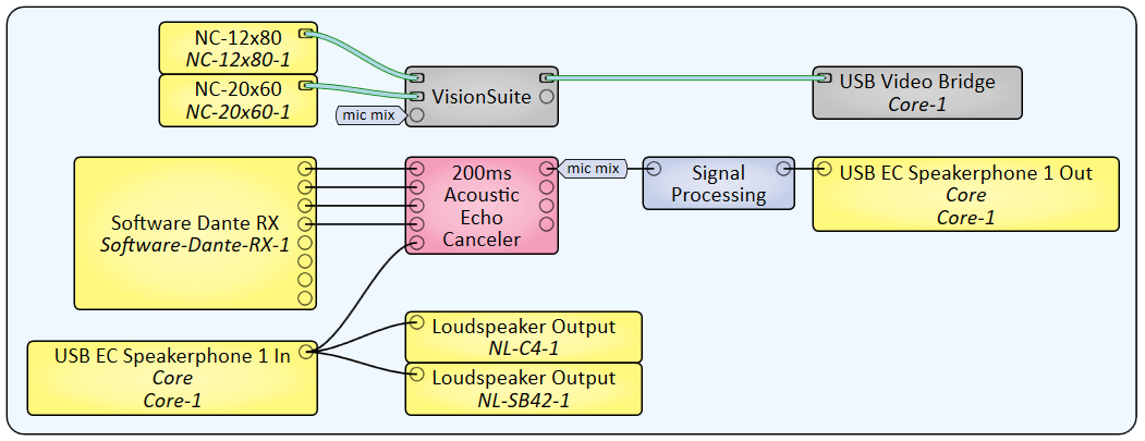
The following demonstrates a use case for the VisionSuite in a two camera system.
Tip: For additional properties that are not listed, refer to the Properties Panel help topic for more information.
Input Count
This setting determines the number of Mediacast Input pins for the design, with a range of 1 to 255. The default is 2. The audio pins cannot be changed, as only 1 is available.
Output Count
This setting determines the number of Mediacast Output pins for the design, with a range of 1 to 40. The default is 1. The audio pins cannot be changed, as only 1 is available.
Image Buttons
This function is unused.
Note: Clicking on the VisionSuite Designer component will open another page within Q-SYS Designer, where a variety of controls will be presented. To modify your VisionSuite design, Emulate or Save to Core & Run.
Icons Along the Top Pane
Hide Inventory Panel (Toggle) 
Toggles the visibility of the left-side Inventory Panel, which contains elements such as Floors, Rooms, Configurations, and Devices (e.g., microphones, cameras, furniture).
Undo / Redo Arrows 
Undo: Reverts the last change made to the design layout, such as moving a device, editing a zone, or adjusting a property.
Redo: Re-applies the most recently undone change.
Bug Record 
This button is used to record a bug log occurring in the telemetry of the last two minutes. If opted, video of the occurrence can also be recorded.
Question Mark 
This icon directs to the VisionSuite online Help, or to the Bug Reports.
in / m 
Toggles the unit of measurement in inches or meters.
Dark / Light Mode 
This icon toggles between dark and light mode, displaying the opposite icon based on the current mode.
Hide Properties Panel (Toggle) 
Toggles between showing and hiding the Properties Panel or Inspector.
Icons Along Left-Side Pane
Expand / Collapse Panel 
This downward-facing chevron is used to collapse or expand sections within the VSD interface, such as inventory categories, configuration panels, or grouped properties. Once expanded, the downward-facing arrow becomes upward-facing to collapse the item.
Plus Sign 
Allows additional inventory items within the categories.
Calibration Tool 
This tool is used to align camera, microphone, and marker positioning with real-world coordinates by referencing microphone or visual markers within the environment. Pressing the Calibrate Button allows the user to place the selected camera relative to the microphone or marker.
Note: In order to calibrate at least one camera must be added along with a microphone or marker. Download calibration markers here.
Trashcan 
Deletes the item added within the specific category.
Visibility (Toggle)
These icons are used to toggle the visibility of elements within the 3D design environment, specifically under the Visualizations section.
The Floor represents the top-level layout container used to organize spaces visually. Within a Floor, a Room defines a specific physical space, and each Room can contain one or more Configs, which are collections of logic, zones, and devices tailored for that space’s functional setup.
Upload Image
Upload a reference image, such as a floor play or layout, that will be used in the design environment.
Size
X / Y: Defines the scale of the image along the horizontal (X) and vertical (Y) axes. A value of 1.00 represents the image at its original scale (100%).
Position
X / Y: Sets the image’s position within the coordinate system, measured in meters. A value of 0.00 positions the image at the origin point (0,0).
Calibrate Scale
Allows the calibration of the image scale based on a known real-world measurement. By selecting two points on the image that correspond to a known distance, the tool automatically adjusts the image scale to ensure accurate dimensional representation within the design.
Room n
The Floor represents the top-level layout container used to organize spaces visually. Within a Floor, a Room defines a specific physical space, and each Room can contain one or more Configs, which are collections of logic, zones, and devices tailored for that space’s functional setup.
Move Entire Room Shape (toggle)
This toggle option allows the entire room boundary to be repositioned within the layout grid as a single unit. When enabled, it lets the user move the room without altering the relative positions of zones, configurations, or other elements contained within it.
Name
Specifies the label of the room. This is a user-defined name used to identify the room within the design.
Schedules
Reboot VSA Weekly (toggle)
When turned to the on position, Q-SYS Designer will reboot the VSA daily or weekly, depending on the chosen schedule.
Recalibrate PTZ Weekly (toggle)
When turned to the on position, Q-SYS Designer will reboot the PTZ weekly, depending on the chosen schedule.
Global Parameters
Speaker Fadeout
Controls how long a speaker remains active after they stop speaking. Higher values keep speakers active longer.
Speaker Reactivity
Controls how reactive the system is when a person starts speaking. Higher values make the system more reactive.
VAD Sensitivity
Controls the Voice Activity Detection sensitivity. Higher values make the system more likely to detect speech.
Corners
This section defines the physical boundaries of a design area by specifying the coordinates of its four corners. Each corner is positioned using X and Y coordinates, measured in meters, to form a rectangular layout within the design space.
- Corner 1 – Origin Point
- X: 0.00 m, Y: 0.00 m
- Represents the starting point (bottom-left corner) of the defined area.
- Corner 2 – Bottom-Right
- X: 9.20 m, Y: 0.00 m
- Marks the bottom-right corner of the design area, defining the horizontal length.
- Corner 3 – Top-Right
- X: 9.20 m, Y: 6.50 m
- Specifies the top-right corner, establishing the vertical height in conjunction with Corner 2.
- Corner 4 – Top-Left
- X: 0.00 m, Y: 6.50 m
- Completes the rectangular boundary, aligned with Corner 1 on the X-axis and Corner 3 on the Y-axis.
Config n
The Floor represents the top-level layout container used to organize spaces visually. Within a Floor, a Room defines a specific physical space, and each Room can contain one or more Configs, which are collections of logic, zones, and devices tailored for that space’s functional setup.
Name
Specifies the label of the configuration. This is a user-defined name used to identify the configuration within the design.
Camera Roles
Camera roles define how a camera behaves within the configuration, influencing how it responds to triggers from visual or audio zones.
- Audio Driven: The camera switches based on activity detected in audio zones. Commonly used in voice-activated camera switching applications.
- Tracking: Enables the camera to follow a subject within a visual tracking zone, typically for presenter tracking scenarios.
- Overview: Assigns the camera to provide a general, static view of the space. It does not change position or zoom in response to logic triggers.
Presenter Logic
A Presenter Rule allows the design to conditions based on activity in Presenter Zones such as entering or leaving a zone.
The toggle switch next to the rule enables or disables the rule without deleting it.
Selecting the ellipsis menu (⋮) provides the following options:
- Duplicate – Creates an exact copy of the existing rule, useful for building similar logic without starting from scratch.
- Add action – Adds a camera action to the visual rule, such as executing a container to move a camera and/or switching to a camera.
- Delete – Permanently removes the rule from the design.
Speaker Logic
Speaker Logic enables the design to respond to audio-based conditions by creating rules that trigger actions based on real-time audio activity within defined zones.
The toggle switch next to the rule allows it to be enabled or disabled without removing it from the design.
A New Audio Rule can be added and configured with a specific Event Type. Available event types include:
- Single-zone speaker spotlight – Becomes active when speakers are identified in one zone. When the Crosstalk checkbox is enabled the rule only becomes active when multiple people are speaking at the same time or in quick succession. When the Crosstalk checkbox is disabled the rule becomes active whenever a person in the zone is speaking.
- Multi-zone crosstalk – Becomes active when speakers are identified in more than one zone simultaneously.
- All zones silent – Becomes active when no audio is detected across all configured zones.
Switch Camera (checkbox)
When enabled, this option activates an automatic camera switch as part of the logic action. Hold Time defines the minimum amount of time (in seconds) the triggering condition must be true before the camera switch occurs.
This section defines the spatial boundaries and behavior type for a speaker audio zone within the design environment.
Move Entire Zone (toggle)
When enabled, allows the entire zone to be repositioned as a single unit without adjusting individual corner coordinates.
Name
Specifies the label of the speaker zone. This is a user-defined name used to identify the zone within the design.
Type
Defines the functional behavior of the zone. These Types are available:
- Trigger: The zone will monitor for audio activity and trigger logic events based on predefined criteria (e.g., presence of speech or silence).
- Spotlight Exclusion: The zone serves as an ignored area within the larger monitored environment. Audio activity within a Spotlight exclusion zone does not trigger Speaker rules. This is useful for excluding non-relevant sources of sound (e.g., HVAC noise, background chatter, or known interference zones) from triggering logic events.
Corners
This section defines the physical boundaries of a design area by specifying the coordinates of its four corners. Each corner is positioned using X and Y coordinates, measured in meters, to form a rectangular layout within the design space.
- Corner 1 – Origin Point
- X: 0.00 m, Y: 0.00 m
- Represents the starting point (bottom-left corner) of the defined area.
- Corner 2 – Bottom-Right
- X: 9.20 m, Y: 0.00 m
- Marks the bottom-right corner of the design area, defining the horizontal length.
- Corner 3 – Top-Right
- X: 9.20 m, Y: 6.50 m
- Specifies the top-right corner, establishing the vertical height in conjunction with Corner 2.
- Corner 4 – Top-Left
- X: 0.00 m, Y: 6.50 m
- Completes the rectangular boundary, aligned with Corner 1 on the X-axis and Corner 3 on the Y-axis.
This section defines visual presenter zones used to trigger camera behaviors based on detected activity within the design environment.
Name
Specifies a custom label for the presenter zone. This name is used to identify the zone throughout the design.
Camera
Associates a camera with the presenter zone. This allows the system to perform visual logic actions (e.g., camera switching or tracking) when activity is detected within the zone.
Type
Determines how the presenter zone behaves. Available zone types include:
- Trigger: Triggers a logic event when activity is detected within the zone. This is commonly used to activate a camera or interface element based on user presence.
- Tracking: Defines an area where a tracked person will continue to be tracked. When a tracked person leaves the area, tracking is stopped and a VIP lost event is generated.
- Exclusion: Defines an area where activity is intentionally ignored by the visual logic. Useful for eliminating background movement or non-relevant areas from triggering camera or logic events.
Plus Sign
Allows additional inventory items by clicking on the plus (+) icon in the Inventory section. Available Inventory Items include:
- Microphone: Adds a microphone element, which can be used for audio logic, speech detection, and calibration reference.
- Name: Assigns a label to the microphone for identification within the design.
- IP Address: Specifies the network address of the physical microphone device, allowing integration with real hardware.
- Port: Sets the communication port used by the microphone. The default is 2202 for Shure MXA920, and 45 for Sennheiser TCC2.
- Model Selector: Dropdown menu used to specify the microphone type. Can be either Shure MXA920 or Sennheiser TCC2.
- Position (in meters) X, Y, Z: Defines the microphone's exact location within the 3D space to ensure accurate calibration and zone alignment.
- Rotation (in degrees) X, Y, Z: Sets the orientation of the microphone along each axis, which is useful for aligning beam-forming or pickup patterns in directional mic arrays.
- After configuration, selecting Create places the microphone into the design layout, making it available for use in audio detection, logic triggers, and calibration tasks.
- Camera: Inserts a camera device into the environment, enabling visual zone logic, tracking, and calibration.
- Name: Specifies a user-defined label for the camera in the system.
- Script Code Name: Used for referencing the camera in scripting or advanced control scenarios within Q-SYS Designer.
- Input Number: Sets the video input number for the VisionSuite component defining where the camera feed is routed.
- IP Address: Allows entry of the network address of the physical camera for IP-based control and video streaming.
- Model Selector: Dropdown to select the camera model, such as NC-12x80, for device-specific behavior and compatibility.
- Camera Role: Defines the role of the camera in the system:
- Audio Driven – Switches based on audio zone activity.
- Tracking – Follows subjects based on motion or visual logic.
- Overview – Provides a static, wide-angle view of the room.
- Position (in meters) X, Y, Z: Determines the camera’s exact location in the 3D design layout to align with real-world placement.
- Rotation (in degrees) X, Y, Z: Defines the camera’s orientation along each axis to simulate pan, tilt, and mounting angles.
- Selecting Create finalizes the camera’s placement and configuration, making it available for calibration and integration into visual or audio logic workflows.
- VisionSuite Accelerator: Represents the processing unit needed to support VisionSuite Speaker Spotlight and Presenter Tracking.
- Name: Specifies a user-defined label for the VSA.
- IP Address: Allows entry of the network address of the physical VSA for IP-based control and video streaming.
- Selecting Create finalizes the VSA's configuration.
- Marker: Adds a positional reference point that can be used during calibration to accurately align camera views with real-world coordinates.
- Name: Assigns a custom label fto the marker for identification within the design.
- Aruco Marker ID: Sets the unique identifier for the ArUco marker being used. This ID must match the physical printed marker placed in the room.
- Board Size: Specifies the real-world size (in meters) of the printed marker’s board. This measurement ensures correct scale is applied during calibration.
- Position (in meters) X, Y, Z: Defines the marker’s exact placement in the 3D environment. Accurate positioning is essential for effective calibration between cameras and physical space.
- Rotation (in degrees) X, Y, Z: Controls the orientation of the marker in space. Proper rotation ensures the marker faces the correct direction relative to the camera.
- Once placed using the Create button, the marker can be referenced during camera calibration to align virtual camera positioning with real-world coordinates.
The Calibration Tool ![]() is accessed by clicking the blue right-angle icon. This tool is used to align camera, marker, and mic positioning with real-world coordinates by referencing audio or visual markers within the environment.
is accessed by clicking the blue right-angle icon. This tool is used to align camera, marker, and mic positioning with real-world coordinates by referencing audio or visual markers within the environment.
Note: Download calibration markers here.
Select Camera
Allows the user to choose the camera that will be calibrated. The selected camera must be part of the current design configuration.
Select Microphone or Marker
Enables the selection of a reference device (e.g., a microphone or designated tracking marker) that will serve as a positional anchor during calibration.
Calibrate Button
Becomes active once both a camera and reference point are selected. Initiating calibration aligns the camera's virtual field of view with its physical placement in the room, ensuring accurate tracking and zone interaction.
Camera Switcher
The Camera Switcher is a system-defined component that is always present in the Inventory section of the workspace to use for manual camera switching.
This dialog allows users to place virtual furniture elements into the design environment, providing visual context and aiding in spatial planning for room layouts and camera line-of-sight considerations. Available Furniture Types:
Chair
Adds a virtual chair to the layout. Useful for representing audience seating or presenter positions in the design.
Table
Inserts a table into the scene, often used to simulate meeting room or classroom arrangements.
Display
Places a virtual display (e.g., screen or monitor) to help visualize sight-lines and positioning relative to cameras and audience zones.
Tip: These items do not impact logic or system behavior but enhance spatial awareness and design accuracy in 3D visual planning.
Furniture Object Properties
These settings are available for all furniture types (Chair, Table, Display) after placement in the design environment. They allow for precise adjustment of object position, orientation, and size within the 3D layout.
Position (in meters)
Defines the furniture object's location within the room layout. X, Y, Z – Sets the object's position along the respective axes. This ensures accurate spatial placement relative to other elements in the design.
Rotation (in degrees)
Controls the orientation of the object. X, Y, Z – Rotates the object around the respective axis. This is useful for angling furniture to reflect real-world arrangements or adjust sight-lines.
Scale
Adjusts the size of the furniture object. X, Y, Z – Scales the object along each axis independently or uniformly, allowing users to resize items to match room dimensions or design preferences.
These options control the visibility of diagnostic and analytical overlays in the 3D workspace.
Persons Uncertainty
Toggles the display of the confidence region around each person's estimated 3D position.
Microphones Raw Data
Toggles the visualization of raw 3D positions detected from microphones, along with their associated confidence regions.
Cameras Raw Data
Toggles the display of raw 3D positions detected from cameras, including their confidence regions.
The Control Pins depend on the Properties chosen.
|
Pin Name |
Value |
String |
Position |
Pins Available |
|---|---|---|---|---|
|
Input n |
||||
|
Source Name |
(text) |
Output |
||
|
Output n |
||||
|
Input n Select |
0 1 |
false true |
0 1 |
Input / Output |
|
Select |
1 to n |
0 to n |
0.0-1.0 |
Input / Output |
|
Source Name |
(text) |
Output |
||