Setting Proper Gain Structure
The main purpose of setting the gain structure is to achieve optimum signal to noise ratio, while avoiding clipped signals. The following signal flow diagram provides a detailed view of a typical analog-to-digital-to-analog processing chain. The pair of critical controls that determine the gain structure are the Max RMS Input Level (dBu) and the Digital Output Gain. The pair of signal level meters that are used to properly set the controls are the Peak Digital Input Level (dBFS) meter and the Peak Digital Output Level (dBFS) meter.
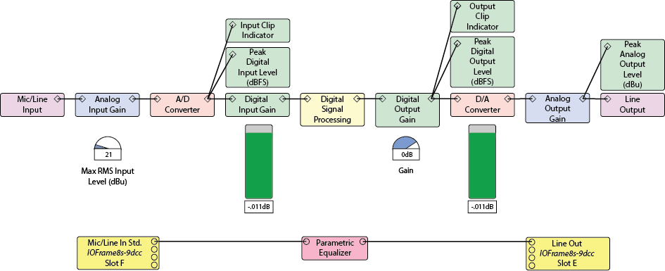
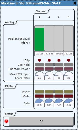
An input source device (microphone, instrument, CD player, etc.) has a nominal RMS output level usually specified in dBu where 0dBu is equivalent to 775mV. When setting the Mic/Line Input Max RMS Input Level, a good starting point is the nominal RMS output level of the device plus some headroom. For example, if the nominal output level of the device is +4dBu and the required headroom is 17dB, the resulting Max RMS Input Level is +21dBu. With the system up and running adjust the Max RMS Input Level such that the Peak Digital Input Level meter shows a signal that is as close to 0dBFS (0dB Full-Scale) as possible but does not cause the A/D Converter to clip, shown by the Clip indicator. Adjust the digital gain to produce a digital signal at the desired level. A typical setting is 0dB. This ensures that the maximum signal into the DSP is at 0dBFS.
Note: The values on the Max RMS Input Level knob represent the output level of the source device. A source with a higher output level requires turning the control counter-clock-wise (down) to lower the input sensitivity. Likewise, a source with a lower output level requires turning the control clock-wise (up) to raise the input sensitivity.
All digital signal processing is done with floating-point number representation which implies that there is ample internal headroom for even the most demanding processing and mixing.
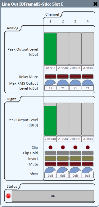
An output destination device (recorder, amplifier, powered loudspeaker, etc.) has a nominal RMS input level usually specified in dBu. When setting the Line Output Max RMS Output Level, a good starting point is the nominal RMS input level of the device plus some headroom. For example, if the nominal input level of the device is +0dBu and the required headroom is 17dB, the resulting Max RMS Output Level is +17dBu. With the system up and running adjust the Digital Output Gain such that the Peak Digital Output Level meter shows a signal that is as close to 0dBFS as possible but does not cause the D/A Converter to clip, shown by the Clip indicator.
Note: Q-SYS has been designed to work with QSC DataPort amplifiers so that when a QSC DataPort amplifier is being used with Q-SYS the DataPort card automatically adjusts portions of the gain. When DataPorts are configured for straight-thru operation a -50dBFS signal at the DataPort output will produce a 1V signal at the amplifier's output terminals. When Custom Voicings or QSC loudspeaker components are wired to an amplifier in Q-SYS, the applied filters will cause the gain to deviate somewhat from 50dB nominal.