Getting Started with Automatic Camera Preset Recall
A quick start guide to Automatic Camera Preset Recall (ACPR) with useful commissioning tips.
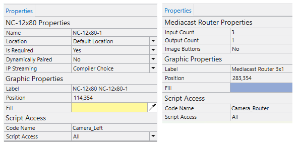
Enable Script Access:
To give the ACPR plugin the ability to position and switch cameras, Script Access must be enabled.
- Set the Script Access property to Script or All for all the cameras in your design AND your Mediacast Router.
- Optionally, change the Code Name to something more user-friendly and easy to identify.
Note: For NM-T1 Microphones, you will need to set the Code Name for the Mic In block.
Configure Microphones for Preset Recall:
- In the Mode property of ACPR, specify which microphones will be used for preset recall. You can choose from the following:
Microphone
Maximum Number Supported
Sennheiser TCC2
10
Sennheiser TCCM
10
Discrete Mics
90
NM-T1
16
Audio Technica ATND1061
10
Nureva HDL 310
10
Nureva HDL 410
10
Shure MXA901
10
Shure MXA920
10
Yamaha RM-CG
10
- In the Microphones property, choose how many are in your design.
Set the Number of Cameras:
In the ACPR component, set how many cameras are in your design. The default is 8, but it can be scaled up to 16.
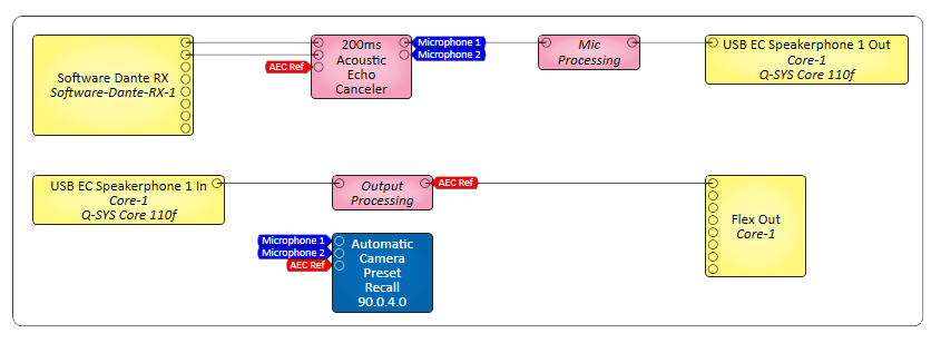
The ACPR plugin receives audio inputs using automatic gated mixing to determine if a microphone or microphone lobe is active and therefore if a user is speaking within the room. It also has an input for ‘Far End Audio’ which is used to determine if someone on the far-end is speaking.
The ACPR plugin relies on audio to action any recall of a camera preset. It is important to ensure that this signal is as clean as possible. This can, of course, be impacted the physical acoustics of the space, but here are some recommendations to help performance:
- Microphone feed can come from POST-AEC to remove residual echoes from the microphone signal, as well as noise-reduction accounting for noisy components in the room.
- OPTIONAL - Bear in mind the audio is not the same as what you will be sending to the far-end. You use blocks to filter specifically for speech frequencies and account for dynamics between quiet and loudspeakers using simple audio processing blocks.
- The far-end audio signal is basically what you will be using for your AEC Reference so you can use the same signal tag.
- Open the ACPR Plugin.
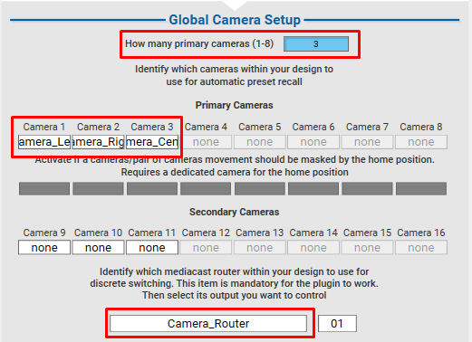
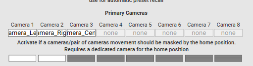
- On the Setup Tab, choose how many primary cameras will be used in your design.
- In the dropdown box under each camera, make your camera selections.
- Note that the camera selections come from the "Code Name" set earlier.
- Bear in mind that the cameras here correspond to the input index of your Mediacast Router.
- Example – your selection for Camera 1 should be the Camera that is wired into input 1 of the Mediacast Router
- Select your Mediacast Router in the dropdown box found.
Connection to the microphones depends on the Mode property set in the Properties:
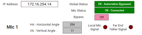
- Sennheiser TCC2, Sennheiser TCCM, Audiotechnica ATND1016or Shure MXA920: In the Microphone tabs of the ACPR plugin, enter the IP address (and credentials) of the microphone that corresponds to the input you wired in earlier. This should connect and begin to update angles automatically (if this is an angle-based microphone).
- NM-T1: Select the Code Name you entered earlier for the Mic In blocks.
- Discrete Microphones: Do not require any connection.
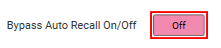
It is a good idea to ensure that the Bypass Auto Recall On/Off is enabled so there is no attempt to recall presets while setting your camera shots.
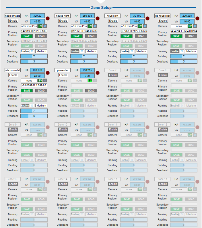
For IP based microphones, each Microphone tab offers the ability to set-up 16 zones + 4 crossover zones. NM-T1 and Discrete microphones will have zones that correspond to each microphone lobe based on the inputs. Each zone constitutes a camera shot driven by the microphone.
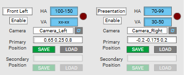
For each zone used, select a camera you wish to use for the preset in the dropdown and use the PTZ controls to frame your shot.
- It is a good idea to sit in the location of the shot (even better with multiple people) so you can get a good view of the shot.
- You can set the frames however you like. Typically a frame of two people with some buffer on the sides works very well as a camera preset, but this is subjective to the use case and the room.
- Once happy with your selection, hit the Save button in the Primary Position controls to save the PTZ Coordinates of that frame.
- Repeat for all your zones on that microphone.
- Optionally you can re-label the zones from Zone n to something more meaningful (e.g., Front Left, Top of table etc.)
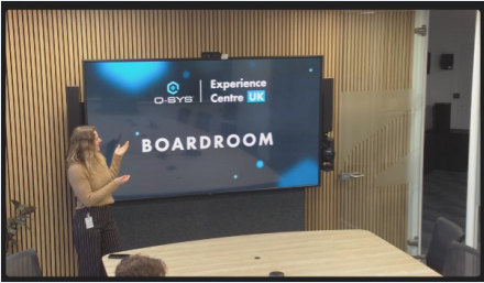
In the example below, we are using a Sennheiser TCC2. We've labeled each with a friendly name for easier identification, and we're using 6 zones.
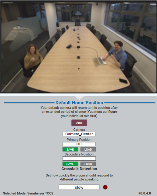
On the setup page, there is also the ability to set up a home shot which activates whenever the following events occur:
- There is silence in the room for an extended period of time.
- Far-end speaks for an extended period of time.
- Crosstalk is detected.
The home shot should be a general overview shot of the space.
Just select the camera and save the coordinates.
If using the plugin with microphones that require angle data, load the preset so you have visibility of the camera shot and stand yourself at the extremities of the that shot. This will give you the starting and ending angle coordinates to determine the range that is required to load that preset.
Note: When configuring zone angles in the ACPR plugin, specifically HA/VA angles, ensure that only whole numbers are used. Decimals are not allowed and will cause errors in the system.
- Horizontal Angles are the primary focus for the ranges to load a camera preset. Any audio signal detected within that range will load the preset.
- Try to avoid angle overlaps between zones unless using vertical angles to distinguish between these.
- Vertical Angles are completely optional – they are typically used to distinguish between a standing vs seated zone if someone is presenting at a screen or whiteboard.
Setup
Auto
To optimize performance, the GUI automatically scales the longest side of any image to 500 pixels. The Auto/Bypass is available to deactivate rendering after setup.
Background Image (Load)
Allows an upload of a floor plan image into the plugin. Once loaded, the image persists even in emulation mode. The image should be scaled to the recommended resolution to match GUI expectations. The two dropdown menus at the top can be used to select the appropriate folder and image.
- The GUI will work without any background graphic.
- If a floor plan is used, use the size of the floor plan itself.
- The plugin framework does not rescale images, so keep the correct aspect ratio.
Status
Provides feedback on the current GUI state, such as recommending image dimensions or confirming successful setup actions.
Talker Height in cm
This sets the vertical position of the talker (e.g., standing or sitting) in centimeters. The default is 110 cm above the floor, and it affects how the microphone zones are visualized and aligned.
Microphones
X Position / Y Position
Defines the microphone’s location on the floor plan in the GUI. The microphone's positions can be set relative to the top-left corner of the image. The height remains at the default value of 250 cm above the floor.
Angles
Updates automatically with the microphone’s horizontal and vertical angle coordinates once connected.
Rotation
Rotates the microphone’s visual representation in the GUI to match its physical orientation in the room.
Color
Customizes the color of the microphone’s zones in the GUI.
Identify
When pressed, this button highlights the microphone’s zones in the GUI and displays their names.
Height
Sets the vertical placement of the microphone in centimeters. The default is 250 cm above the floor, which corresponds to typical ceiling-mounted configurations.
Active (LED)
This LED mirrors the “Mic Signal Present” indicator. It lights up when the microphone detects audio, confirming that it is actively picking up sound.
Room Setup
Enable
Activates the selected room zone configuration, making it live for processing and visualization in the GUI.
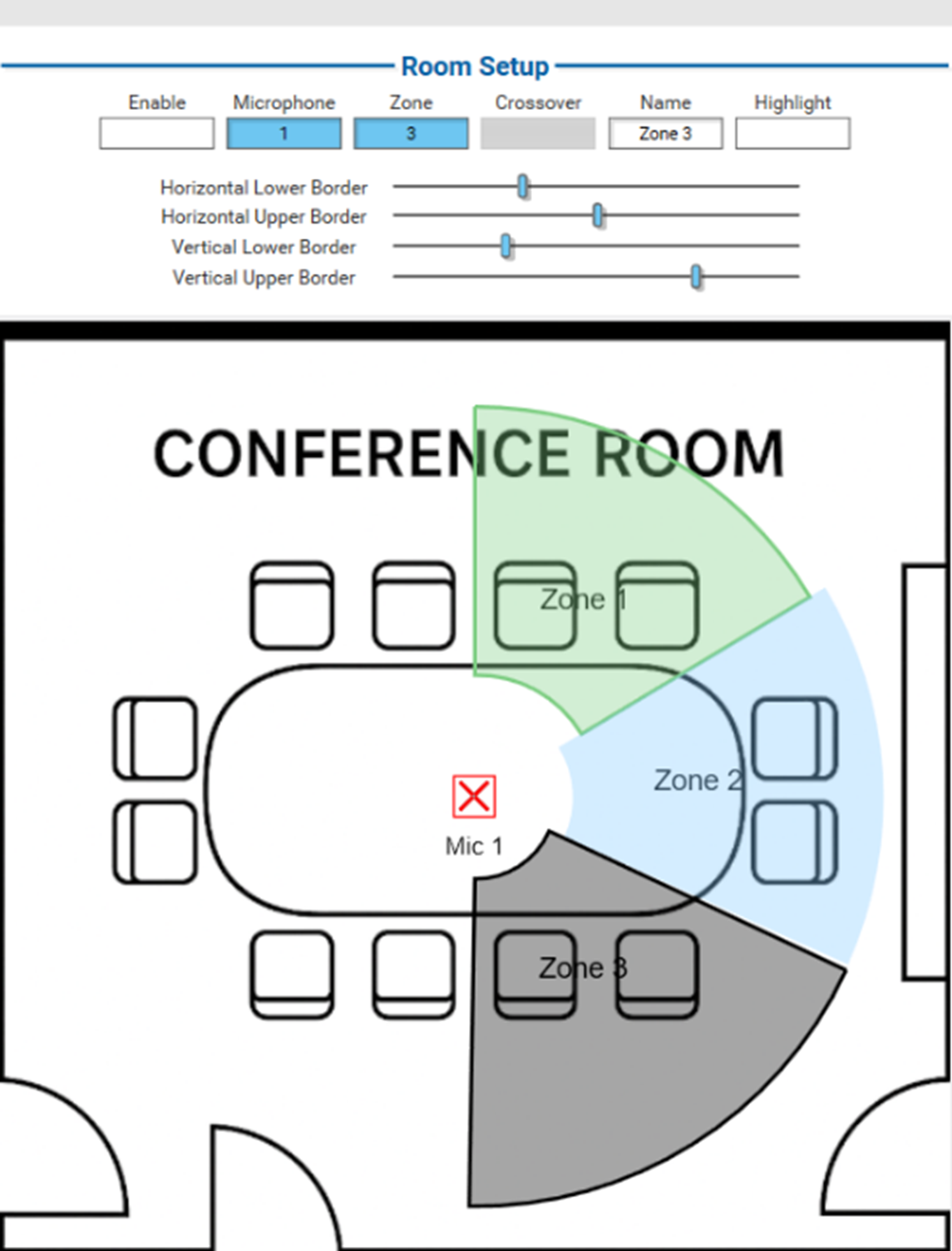
Microphone
Selects a specific microphone and makes its zones selectable in the zone control.
Zone
Defines the spatial area in which the microphone will detect and respond to talkers.
Crossover
If dealing with Crossover Zones (17–20) pressing the Crossover button will switch focus to the secondary microphone and draw the zone from this secondary microphone it is linked to. However it will appear in the color of the primary microphone where the zone belongs to.
Name
Assigns a label for the zone for easier identification, especially when managing multiple zones or microphones.
Highlight
Visually emphasizes the selected zone in the GUI.
- Pressing Highlight marks the currently selected zone black.
- The currently active zone (preset recalled) will be green.
- A dot will appear at the speaker’s location.
Horizontal Lower Border / Horizontal Upper Border
These define the left and right edges of the zone in the horizontal plane, relative to the room layout. Use the sliders to set these values. All controls reference back to the original zone fields on the “Microphone 1” page.
Vertical Lower Border / Vertical Upper Border
These define the bottom and top edges of the zone in the vertical plane, helping to shape the zone’s 3D detection area. Use the sliders to set these values. All controls reference back to the original zone fields on the “Microphone 1” page.
In our example, we are using Metric units and the following floor plan:
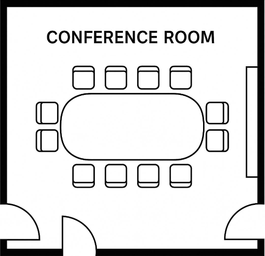
- The room used in the example is 7x7 meters, so the plugin’s properties are configured to metric units with a room size of 700x700 centimeters.
- To prepare the floor plan, the walls are cropped out using a graphic editor such as Photoshop or GIMP, and the image is then scaled to 500x500 pixels.
- The image is uploaded to the Core’s file system, and the appropriate folder and file are selected using the two dropdown menus at the top of the GUI. Pressing “Load” imports the image into the plugin.
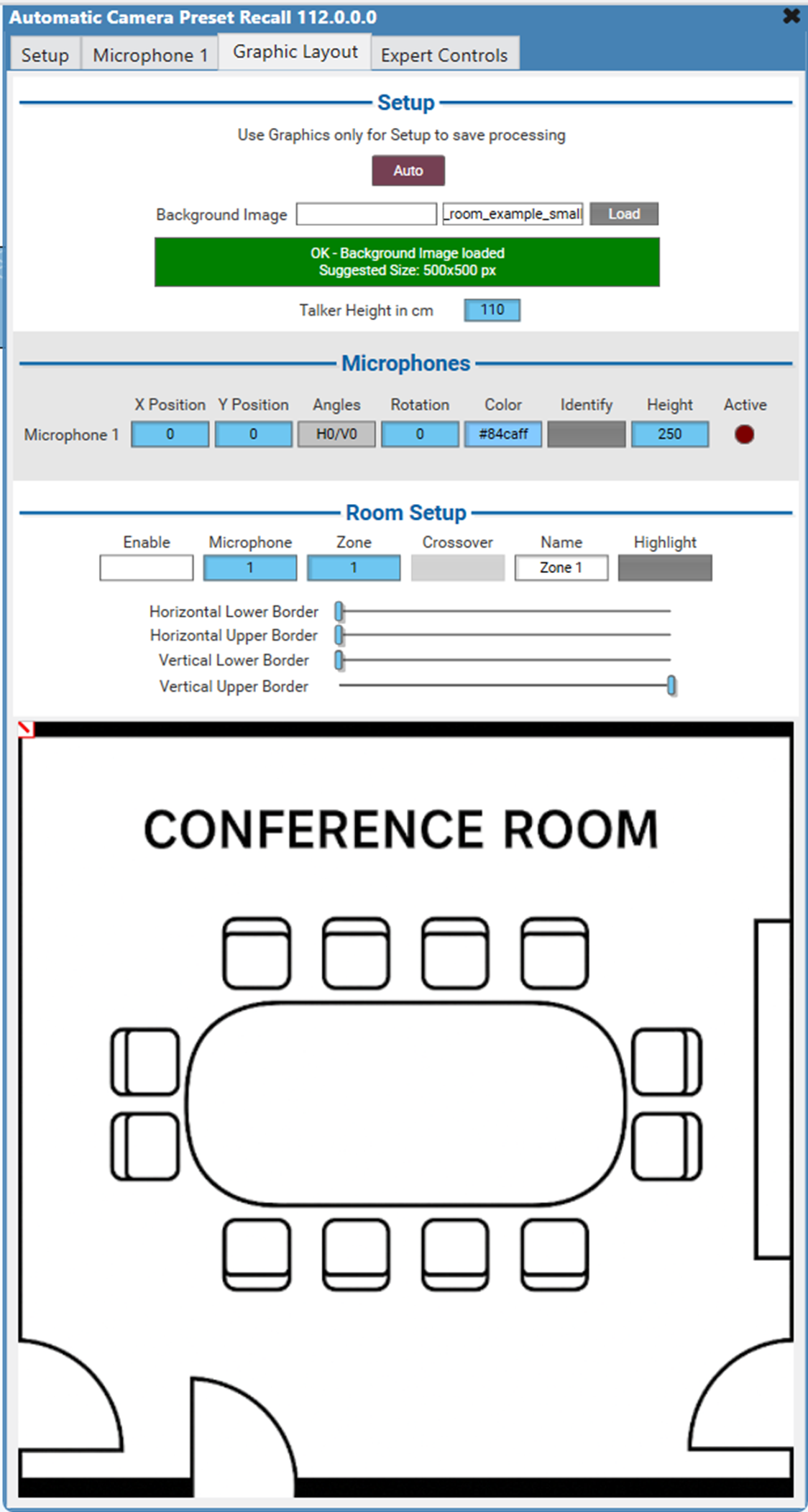
- With the image in place, the talker height remains at the default setting of 110 cm above the floor. The microphone’s X and Y position is adjusted so that it is centered within the room.
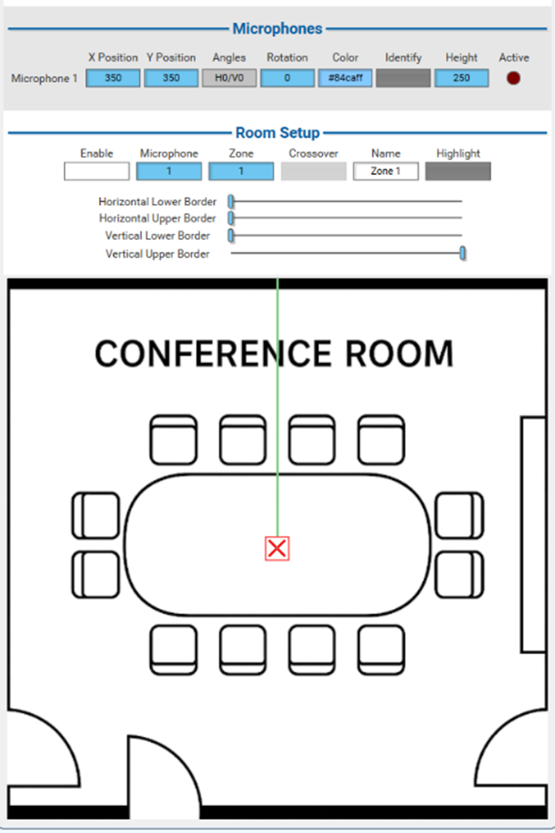
- To setup the zones simply select the microphone and zone and use the sliders to set horizontal and vertical borders. All the controls are referencing back to the original zone fields on the “Microphone 1” page. Pressing Highlight marks the currently selected zone black. The currently active zone (preset recalled) will be green. A dot will appear at the speakers location. The microphone can also be rotated to match its real-world orientation, and the color of its zones can be customized.
If Reinforcement Mode is activated in the properties, 10 additional audio pins and camera zones will be available. These are intended for use with Handheld or Headset Microphones for presenters and will always take priority over the regular room microphones. The zone setup is no different from the regular zones.
For a comprehensive view of each Expert Control, see ACPR Expert Controls.
If using ACPR in larger spaces, there is a good chance you have multiple microphones being used for ACPR. This is great to allow for more presets, but let’s say a user speaks while in between two microphones – you may find the LED for active zones darts between two microphones which ACPR detects as crosstalk (eek!).
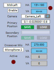
The crossover zones (17-20) allow you to specify to the plugin that the speaker may be detected by another microphone. Set these zones up as you would any other, but also include the microphone they can be detected by (and the angle ranges of that second microphone if using a mic that provides angle data). Therefore, if a speaker is detected within either of these crossover points then the plugin will no longer treat this as crosstalk and will load the preset as expected.
Test Your Presets
Disable the Bypass button, move around the space and speak in your designated zones. Monitor the switching to see if they are functioning as you expect and tweak any angles and preset shots as necessary.
You can adjust the PTZ Switch Delay which determines in seconds how long someone needs to speak before it actions a preset recall. Please consider that the higher the value the longer it will take to action a switch, the lower the value the preset switching may be very snappy and the plugin will be more sensitive to crosstalk.
Give crosstalk a test and see if it recalls the home position as you see fit. You can adjust the detection time in the ‘Setup’ page of the plugin.
Primary/Secondary Cameras
For each primary camera you can determine a secondary camera that runs alongside it. These will typically be installed right next to each other physically so they can share similar camera angles when recalled. This means that if the primary camera is in use, Q-SYS can position the secondary camera behind the scenes before actioning the switch. The result is that the far-end never sees the PTZ movement of the cameras for a better experience.
The inputs for the secondary cameras on the Mediacast Router are +8 from the input of the primary camera it will be paired with:
- If paired with input 1 then the input for the secondary camera will be 9. The secondary pair for input 3 will be input 11 etc., you will just need to amend your Mediacast Router to account for these additions.
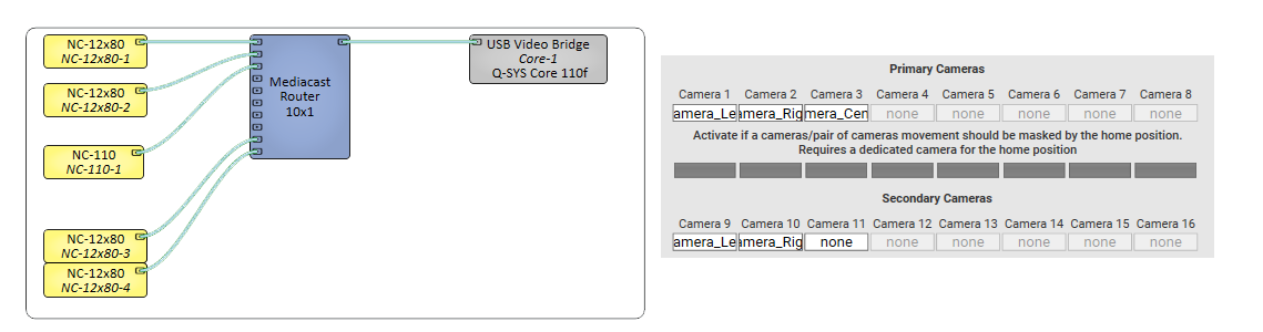
If you don’t have secondary cameras to pair with your primary cameras, then you can use the home camera to mask the switch while the cameras are being positioned. The result will be a brief switch to the home camera for a few seconds. These can be enabled in the ‘Setup’ page using these toggle buttons. Please bear in mind that this will add additional latency to the preset switch.
The Camera designated for the ‘Home’ Position Masking should be used ONLY for the home position and stay in this position.
HA and VA angles must be whole numbers. Decimals are not allowed and will cause errors in the system.