
A Schematic Element is anything that is in a Q-SYS Designer schematic. This can include Components, graphics including graphics/pictures from other applications, and text. This topic describes the various things that can be added to a Schematic, and how to use the common features of the Schematic Elements, and of Q-SYS as it relates to Schematic Elements.
The following information is covered in this topic:
| Components | Moving Schematic Elements |
| Deleting Schematic Elements | |
| Selecting Schematic Elements | Headers, Text, Boxes, and Other Graphics |
| Copying and Pasting Schematic Elements |
The Design Elements are a list of the Inventory items you have added to your design, the Schematic Elements are a list of the Components you can add to your design, and the Properties pane lists the parameters you can specify when an element is in the schematic and selected.
Each of these three can be docked to top, bottom, and either side of the schematic. In addition, you can merge the three and the titles become tabs for selecting which you want to use. Click the title area and drag to the position you wish. When you start to drag one of the three, docking icons display; these are used to automatically dock the list when you move the cursor over one of the icons.
Right-clicking one of the title areas gives you various choices depending on whether the list is docked or floating.
Components are found in the Schematic Library, Inventory, and Snapshots. For the most part, the descriptions found here apply to all components. For details about a specific Component, refer to the individual topic. In the Schematic Library, Components are grouped into Audio Components, Control Components, and Layout type Components. In the Inventory section Components are under the individual Inventory item when it is added to the Inventory, Snapshots are in the Snapshot section under the Global Snapshot, and any Snapshots you add.
The upper section of the component has audio inputs on the left and audio outputs on the right. The type of connector pin depends on the type of the Component, and not all Components have both or any inputs and outputs. The Components found in the Inventory section can have digital and/or analog audio connectors. The Components in the Schematic Library have only digital audio connections. Refer to Connection Types for detailed information.
The lower section contains the Control Pins. Control Pins display on most components only after you have selected them in the Properties > Control Pins section of the Component. Some Components only have Control Pins.
HoverMon enables you to hover over a digital input/output, audio or control pin, on a component and get information about the input or output of that pin. In addition, for audio pins, you can get audio output to your PC. The HoverMon does not work with analog inputs/outputs such as the output of a DataPort Out card. HoverMon is not available for pins that have no pertinent information to display. For example, momentary and trigger type buttons.
See Configure Audio Monitor for information about configuring HoverMon audio.
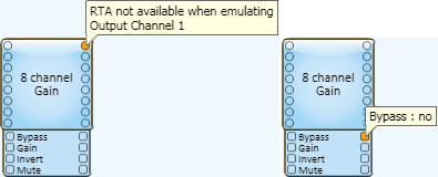
In the Design Mode, for both audio and control pins, HoverMon displays only the pin name and designation.

In the Emulate Mode, you can see the pin name, designation and, for the Control Pins, you can see the state or value of the control for that pin.
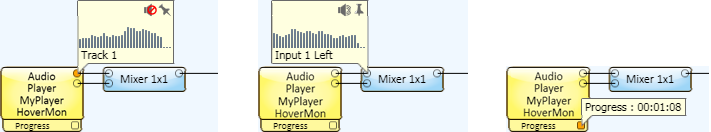
In Run mode, when you move the mouse over an audio connection it is identified in the hover text along with a graphical Real Time Analyzer (RTA - Band-Pass) spectrum describing the input or output of that pin. In addition, you have access to the controls for turning on audio to your PC's sound card, and "pinning" the HoverMon on that pin. Hovering over a Control Pin gives you "live" information about that control signal, for example, time, level, etc. You cannot "pin" the HoverMon to a Control Pin.
When you place a component in the Schematic and select it, the component's Properties display below the Schematic Library in the right side pane. Some Properties dynamically control the values of other Properties and are documented for each Schematic Element.
Each Component has controls available for use during the run and Emulate modes. When you double-click a Component in the Schematic, the control panel for that Component displays.
You cannot make adjustments in the design mode. In the Emulate mode, you can make control settings, test control logic like Web Panels and Control Scripts, but audio is not processed. In the run mode ( Load from Core & Connect..., and Save to Core & Run) all the functions of the system are operating.
Use controls to set the various parameters for a component. Refer to the Using Controls topic for complete details.
Components are added to the Schematic from the Schematic Library, Inventory, and Snapshots. When a component is in the Schematic, you can make connections between it and other components to use in your design, make initial adjustments to controls, and so on. To add anything to the Schematic, select it and hold the left mouse button and drag it into the Schematic. You can also copy and paste most elements when they are in the Schematic. You cannot add Components to User Control Interfaces.
You must add items to Inventory, and Snapshots before you can add them to the Schematic. The exception is the Core it is always in the Inventory, you cannot delete it, or add additional primary Cores. Each item in the Inventory has a child Component or Components associated with it. You can drag either the item itself, or its individual component(s) into the Schematic. If you drag an item with multiple components into the Schematic, all of its associated components are placed into the Schematic.
The Components in the Schematic Library are virtual in nature — they do not represent physical equipment. Components in the Schematic Library are grouped by function and listed alphabetically within their functional areas. The main functional areas are Audio Components, Control Components and Layout Components.
Using Find (Ctrl+F) you can find items in one of two ways.
You can easily find specific item if it:
NOTE: When you select a control in a control panel, it may exist in several places. For example, one control can exist in any of the following: Named Controls, Snapshot Bank, UCI, the Schematic.
The following rules apply for selecting any Schematic Elements:

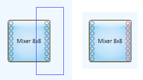
NOTE: If you want to select a of group pins, between the first and last pins, on the right side of a component, you can use the intersect method and select those pins. When you do this, the component is selected as well. Press and hold the Alt key, the selection box becomes a surround type box. Surround the pins you want to select, nothing else is selected. Another method is after selecting with a crossing box, press and hold the Ctrl key, then click the component. The component is no longer selected, but the pins remain selected.
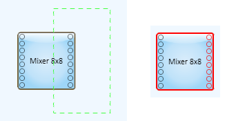
Notice that the Mixer Component (right) is selected as well as the connectors. Contrast this to the example for the surround method.
Refer to the Signal Pins and Wiring in the Schematic topic for connection details.
Copying and pasting components is an effective way to create multiple instances of the same component with the same configuration. After you have added a component to the schematic and configured it, you can copy and paste it, and the pasted component keeps the configuration settings of the copied one. If you have made any control settings in either the Run or Emulate mode, when you copy and paste the component, the control settings are copied as well.
There are several convenient ways to copy and paste components in the schematic while in design mode.
Select the component then:
There are a few items that cannot be copied or pasted. For example, the Core or I/O Frame and any of their sub-components. If you copy and past other inventory items a new item is added to your Inventory list each time you paste it - handy for adding multiple loudspeakers with the same configuration.
In the Design Mode you can copy controls from a Component's Control Panel and paste them in the Schematic or into a User Control Interface (UCI). The controls you paste are tied to the controls from which they were copied. This means you adjust one control, and the other control changes with it.
When you copy/paste controls into a UCI, the pasted controls are used by an end-user to manipulate the settings of the Component from outside Q-SYS Designer. You can arrange the desired controls in the UCI to better suit the needs of the end-user.
You can copy/paste controls into the Schematic to arrange them in other ways than they appear in the Component's Control Panel. This can be helpful when troubleshooting, or setting up and testing the Q-SYS installation.
You can copy the controls into a Popup Button window, then open and close the popup window to show or hide the controls.
If you place a button into the Schematic, UCI, or Popup Button window, you can drag a bitmap type graphic into the button and it will be sized to fit into the button. You can also copy an object (not a file) from a vector type graphic program into the Schematic, then drag it into the button.
In the Run or Emulate mode, you can copy the settings of one or more controls from a Component's Control Panel, and paste them into another Component's Control Panel to duplicate the control settings. In addition, you can copy all controls without going into the components control panel.
IMPORTANT: The Component you are copying to must be the same kind of Component as the one you are copying from.
To copy one or more control settings:
TIP: If the first control you select is a button, selecting it changes the state of the button. To avoid this, press the Ctrl key then select the control.
NOTE: The Property settings, time readouts, and so on, are not copied.
When you select a component in the schematic, you can move it using a few different methods.
Select the Schematic Elements you want to group, then press Ctrl+G (or Main menu >Tools >Group). The items can be moved, cut, copied, pasted, deleted as a group, without changing their relative position. To ungroup a set of grouped items, select the group, then press Ctrl+Shift-Z.
IMPORTANT: You cannot connect standard wiring between components in a group and components outside of a group. You must name the connection pins to make connections to components outside of a group. You can wire to/from components within a group.
Select the Schematic Element(s) you want to delete and press the Delete key. If there are any "wires" connected to an element, they are deleted as well. If the element is an item from the Asset Manager Panel, it is returned to the Asset Manager Panel and can be reused.
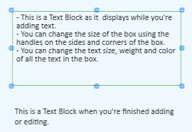
You can add Headers, Text Blocks, and Group Boxes to organize, annotate, and enhance the appearance of your design / User Control Interface using the following Graphic Tools. For complete information see Graphic Tools.


If you have a list of items, or a set of sequential numbers, you can select the list/sequence and paste it into a group of Headers, Text Blocks, or Group Boxes. The list or sequence must be either tab delimited, or on separate lines (carriage returns).
NOTE: There are other methods of creating a list that can be pasted into Q-SYS boxes, and some that won't work. For example, you cannot paste a list from Microsoft Excel. However, if you copied the list from Excel into Microsoft Word, it becomes a table that you can paste into Q-SYS boxes. Other applications have not been tested.
QSC.com | Software and Firmware | Resources | QSC Self Help Portal
© 2009 - 2018 QSC, LLC. All rights reserved. QSC and the QSC logo are trademarks of QSC, LLC in the U.S. Patent and Trademark office and other countries. All other trademarks are the property of their respective owners.
http://patents.qsc.com
