Open topic with navigation
Networked Audio Design
Audio Channels and Streams are created by wiring to and from networked I/O devices. Using efficient wiring, and the capabilities of the Q-SYS Core, you can maximize the capabilities of your Q-SYS system. This topic explains the principals of Network Audio Channels (NAC) and Network Audio Streams (NAS), and how to wire the components in your design to achieve maximum efficiency in your Q-SYS system.
Core Channel Capacities
|
Unified Core
(small scale)
|
Core 110
|
24
8 analog in,
8 analog out,
8 analog flex in/out,
16x16 USB audio
|
128 x 1281
|
16
|
16
(upgradable
to 32)
|
N/A (Built-in I/O on this model) |
4 |
|
Integrated Cores
(medium scale)
|
Core 500i
|
Up to 32 analog,
up to 128x128 AES/CobraNet/
Dante/AVB
|
128 flex in/out
|
24
|
16
(upgradable
to 128)
|
8
|
64
|
|
Core 510i
|
Up to 32 analog,
up to 128x128 AES/CobraNet/
Dante/AVB
|
256 x 256
|
64
|
16
(upgradable
to 128)
|
8
|
64
|
|
Enterprise Cores
(large scale)
|
Core 1100
|
Up to 4 analog,
up to 16 AES,
up to 64x64 CobraNet/Dante/AVB
|
256 x 256
|
72
|
16
(upgradable
to 128)
|
1
|
64
|
|
Core 3100
|
Up to 4 analog,
up to 16 AES,
up to 64x64 CobraNet/Dante/AVB
|
512 x 512
|
144
|
16
(upgradable
to 128)
|
1
|
64
|
|
Dell Enterprise Cores
(IT friendly)
|
Core 5200
|
N / A
|
512 x 512
|
160
|
16
(upgradable
to 128
|
N / A
|
64
|
Network Audio Channel Fan-out
Fan-out is the distribution of a single Network Audio Channel (NAC) to multiple outputs. In Q-SYS Designer you can distribute the output several ways. This topic describes fan-out, and how to incorporate it in a Q-SYS design in the most efficient way.
Network Audio Channels are made up of virtual and physical connections.
The Q-SYS Core and I/O Frames are physically connected via the Ethernet. Each I/O Frame has four (I/O Frame 8s has 8) available slots for I/O cards. The I/O cards are identified in Q-SYS Designer by I/O Frame and Slot within the I/O Frame. When you make a connection in Q-SYS Designer from a Gain DSP component, for example, to a representation of an I/O card, like a Line Out card, you are telling Q-SYS that "this Gain output" is going to Channel 1 of the card in "Slot x" of "I/O Frame xyz". In a Q-SYS Designer Schematic, the physical Ethernet connection between components is not shown, neither are the I/O Frame or Core; it is the virtual connection that is shown. The virtual connections shown in this topic are more like assignments from a DSP component running on one physical piece of hardware, to a DSP component running on a card within another physical piece of hardware.
Network Audio Channel Definition
- A unique, point to point, audio signal on the network.
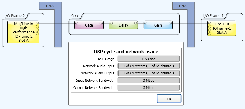
In the example above the Mic/Line card in an I/O Frame only has one channel wired, and represents one Input Network Audio Channel. The Line Output card in another I/O Frame with only one channel wired, represents one Output NAC. If either card is installed in a Core, there are zero NAC's counted because the audio is not on the network, but in the Core only.
Note: The two network connections also represent two Network Audio Streams, one input and one output, because the signals go to different I/O Frames.
- Can be connected between Cores in multi-system installations.
Counting Network Audio Channels in Your Design
You can determine the number of Input NACs and Output NACs by pressing Shift+F6. The Check Design dialog box displays the number of Input and Output NACs along with other information.
- When counting Input NACs, the system counts all signal pins on all input cards that are in the design and wired to another component in the schematic.1 If you put one Mic/Line Input card into your design, and wire all the signal pins, the Input NAC count is four because it has four connectors.
- When counting Output NACs, the system counts all the signal pins on any of the output cards that are placed in the design and wired to another component.
- When an input or output card is installed in the Core, there are no NACs because the connection is internal to the Core, and not on the network.
1. To use Check Design as described above, you do not have to have a physical I/O Frame connected. Placing the virtual components of a virtual I/O Frame into the schematic and wiring the signal pins to another component (could be anything) in the schematic works for counting streams and channels with Check Design. To actually use any card (pass audio), the card must be installed in a physical piece of equipment (I/O Frame or Core), and wired in the design.
Wiring in Q-SYS Designer
Network Fan-out
- Fan-out on the network is one audio signal from the Core going to multiple I/O Frames on the network. This method uses multiple NACs, and the audio signal is sent multiple times. Input signals always use one NAC per input because they are all unique, whereas an output can be the same signal going multiple places.
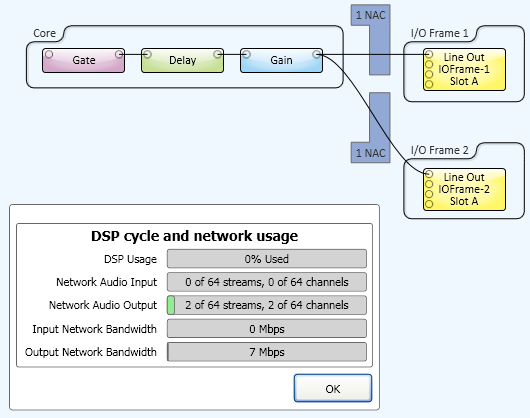
In this example, the signal from the Core is the same, but because it is going to two separate I/O Frames, it requires two NACs.
Note: The two network connections also represent two Output Network Audio Streams because the signals go to different I/O Frames.
I/O Frame Fan-out
- Fan-out in the I/O Frame is one audio signal from the Core going to a single I/O Frame. Inside the I/O Frame the audio signal is fanned-out to a possible 16 output channels. In this case, only one NAC is used on one NAS.
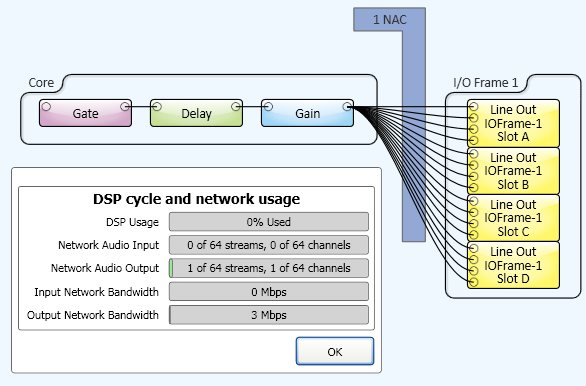

The top example is how the design looks in Q-SYS Designer, the bottom is a network representation. In the example, there are 16 channels from one source, going to a single I/O Frame with four 4-channel Line Out cards, using only one NAC because it is only going to one I/O Frame.
Note: The one network connection also represents one Output Network Audio Stream because the signal goes to only one I/O Frame.
Fan-out Gain Control
Output to Amplifiers
When one NAC is fanned-out into multiple channels, there is an individual gain control for each channel. The available controls with the Q-SYS output cards vary depending on the card.
Loudspeakers
When QSC DataPort amplifiers, and QSC loudspeakers are used in a design, there are individual gain controls for each loudspeaker, including multi-way loudspeakers.
Network Audio Stream
Definition
A Network Audio Stream (NAS) is a bundle of one or more NACs going to or from a single peripheral connected to the Q-LAN network, and wired in the design running on the Core.
Hardware peripherals include I/O Frames and Page Stations. A Q-LAN Receiver or Transmitter does not represent physical hardware, and needs only to be in a design (not wired) to be counted as an NAS with NACs. The Q-SYS Touchscreen and DataPort Amplifier Backup panel peripherals do not count against the NAS count.
The maximum number of NACs in a single NAS is 16 because you can only have 16 inputs or outputs.
Note: An I/O Frame with four AES3 Input / Output cards installed has one Input NAS with 16 channels, and one Output NAS with 16 channels giving a total of 32 channels for a single peripheral.

The example above shows the different types of NASs. There is one NAS for all inputs going to a single peripheral, and one NAS for all outputs going to a single peripheral. All components must be wired in the design with the exception of the Q-LAN Transmitter and Receiver.
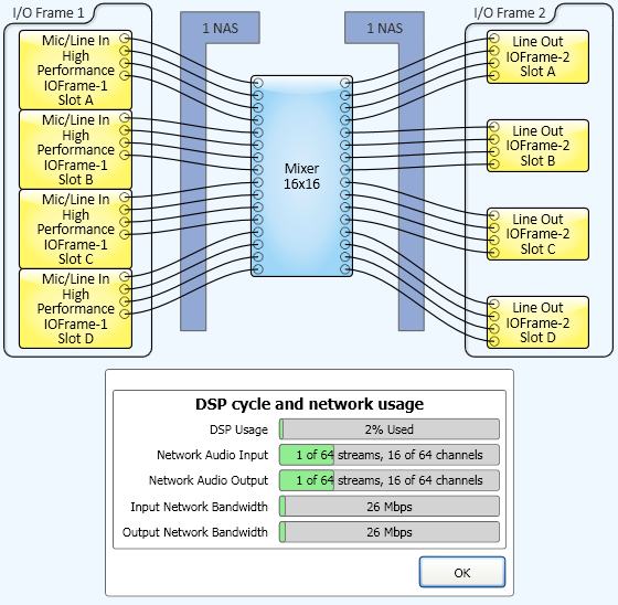
This example has two I/O Frames with 16 channels each going to the Core. For each I/O Frame, there is one NAS; a total of two NASs.
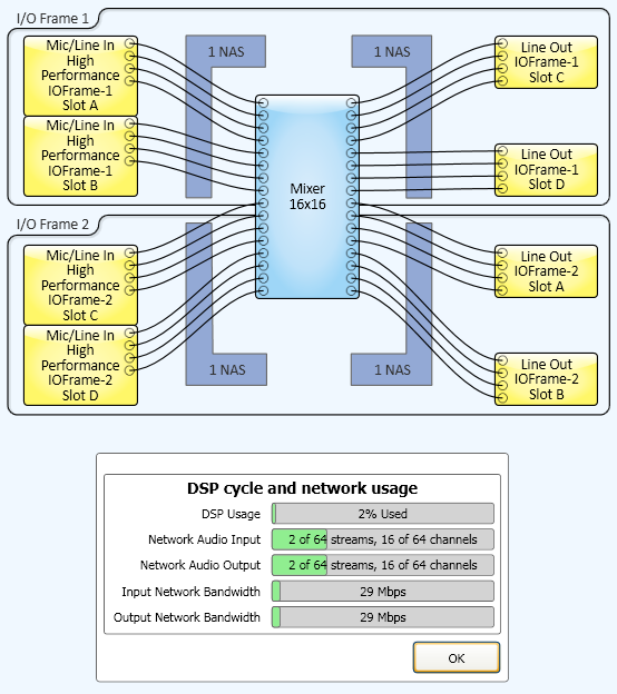
In this example, each of two I/O Frames have both input and output cards, resulting in two input streams and two output streams.
While this has the same I/O Frame count and audio channel count as the previous example, it is less efficient because more streams are required.
