The Properties listed below are specific to the RS-232 Serial Port component. The other Properties available when the RS-232 Serial Port is selected are related to the Core, I/O Frame, or the I/O-22 Status topics. See Status (Core), Status (I/O Frame), and Status (I/O-22).
|
Property |
Function |
Choices |
|---|---|---|
|
Name |
Text name identifying the RS-232 Serial Port component. |
User defined |
|
Serial Port |
Identifies which serial port you are communicating through. |
0 to 4 |
|
Control |
Function |
Default / Range |
|---|---|---|
|
TX Bytes |
Displays a running total of the number of bytes sent. |
N / A |
|
RX Bytes |
Displays a running total of the number of bytes received. |
N / A |
|
Reset |
Resets both TX Bytes and RX Bytes to zero. |
N / A |
The available Control Pins depend on settings in Properties.
|
Pin Name |
Value |
String |
Position |
Pins Available |
|---|---|---|---|---|
|
Reset |
Trigger |
Input/Output |
||
|
Receive Bytes |
Text Box |
Output |
||
|
Transmit Bytes |
Text Box |
Output |
||

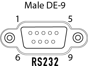
Pinout
- Pin 2 - RX (Receive)
- Pin 3 - TX (Transmit)
- Pin 5 - GND (Signal Ground)
- All other pins on a Core are not supported
- Pin 4 on an I/O-22 provides +5.5VDC @ 70mA (not on any other Q-SYS product, though)
This signal to DE-9 configuration is known as DTE. All 9-pin D-Shell RS-232 pinned as DTE have this configuration. All PC serial ports are DTE as is the Core, I/O-Frame and I/O-22. Usually peripherals are DCE, which reverses the receive and transmit pins, allowing a straight-thru cable to be used.
You must check the pinout of any equipment, including the cable, to be connected to a Q-SYS serial port for input or output. Many times in serial troubleshooting, problems may be solved by inserting a "null-modem" adapter or cable to swap the TX and RX pin positions. For custom terminated DE-9 connectors, pins 2 and 3 may need to be swapped on one end of the cable. In any case, a TX pin on one end MUST be connected to an RX pin on the other and vise-versa for data to flow properly.
