Serial Port (Core, I/O Frame, I/O-22)
Q-SYS Core processors and peripherals include an RS-232 connection for extension of Q-SYS Control to third-party devices, such as projectors, TVs, and A/V receivers. You can control and read from these devices using Lua script from a Q-SYS scripting component.
Tip: To learn about scripting in Q-SYS, see Control Scripting.
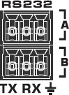
The Serial Port component represents the RS-232 serial connection pins on the rear of the Q-SYS Core, I/O Frame, or I/O-22. The connector varies depending on the hardware.
| Pin | Description |
|---|---|
|
TX |
Transmit pin. Connect this pin to the RX (receive) pin on the other device. |
|
RX |
Receive pin. Connect this pin to the TX (transmit) pin on the other device. |
|
Ground |
Earth ground reference. |
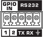
Note: On the NV-32-H (Core Capable), the RS-232 and GPIO IN pins share a 5-pin Euro connector. You can use both connection types simultaneously.
| Pin | Description |
|---|---|
|
TX |
Transmit pin. Connect this pin to the RX (receive) pin on the other device. |
|
RX |
Receive pin. Connect this pin to the TX (transmit) pin on the other device. |
|
Ground |
Earth ground reference for GPIO input and RS-232 connections. |

| Pin | Description |
|---|---|
|
2 |
RX (Receive) |
|
3 |
TX (Transmit) |
|
4 |
(I/O-22 only) Provides +5.5VDC @ 70mA |
|
5 |
GND (Signal Ground) |
Note: All other pins on a Core are not supported.
This signal to DE-9 configuration is known as DTE. All 9-pin D-Shell RS-232 pinned as DTE have this configuration. All PC serial ports are DTE as is the Core, I/O-Frame and I/O-22. Usually peripherals are DCE, which reverses the receive and transmit pins, allowing a straight-thru cable to be used.
You must check the pinout of any equipment, including the cable, to be connected to a Q-SYS serial port for input or output. Many times in serial troubleshooting, problems may be solved by inserting a "null-modem" adapter or cable to swap the TX and RX pin positions. For custom terminated DE-9 connectors, pins 2 and 3 may need to be swapped on one end of the cable. In any case, a TX pin on one end MUST be connected to an RX pin on the other and vise-versa for data to flow properly.
The Serial Port component has no specific configurable properties. Refer to the Status component for the Core or peripheral for properties related to your hardware. See Status (Core), Status (I/O Frame), and Status (I/O-22).
TX Bytes
Displays a running total of the number of bytes sent.
RX Bytes
Displays a running total of the number of bytes received.
Reset
Resets both TX Bytes and RX Bytes to zero.
|
Pin Name |
Value |
String |
Position |
Pins Available |
|---|---|---|---|---|
|
Reset |
Trigger |
Input/Output |
||
|
Receive Bytes |
Text Box |
Output |
||
|
Transmit Bytes |
Text Box |
Output |
||
