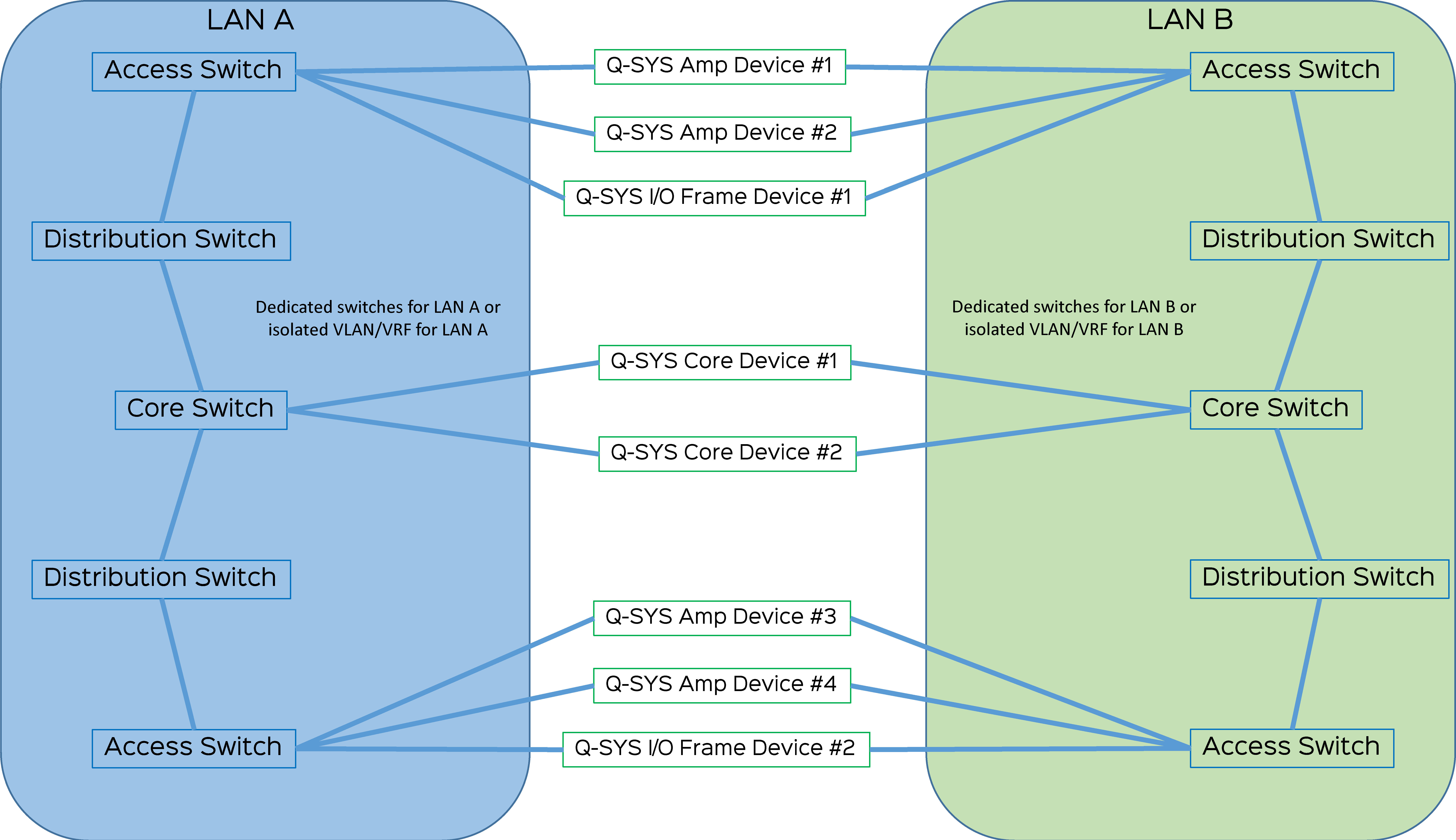
Network Switches & Infrastructure
Q-LAN relies on the performance of modern network switches to ensure real-time delivery and synchronicity of media streams across all connected Q-SYS devices. The Q-SYS network must meet the following requirements for network switches, cabling, hop count, network diameter, and backbone bandwidth.
Q-SYS has several networking options for the Q-SYS Ecosystem. For more information about these options, see Q-SYS Networking Solutions on the Q-SYS website.
NS Series Gen 2 Network Switches
The Q-SYS NS Series Gen 2 offers a range of enterprise-grade, NETGEAR-manufactured network switches that have been pre-configured specifically to meet the performance requirements for Q-SYS, AES67 and Dante. With a primary focus on Q-SYS audio, video & control (AV&C), these network switches provide an out-of-the-box solution for Q-SYS integrators and IT support staff building standalone AV networks.
For more information, see Q-SYS NS Series Gen 2 Network Switches on the Q-SYS website.
Manual Network Switch Configuration
There are a number of managed Ethernet switches on the market today that provide the necessary performance for real-time media distribution on your Q-SYS network. Q-SYS is unable to provide live configuration support for third-party switches, but does provide switch requirements information and configuration examples for specific switch models.
See Additional Switch Documents on the Q-SYS website for switch configuration examples, networking resources , and a list of switches with known Q-SYS compatibility and performance issues.
Note: Manual network switch configuration is only recommended for experienced integrators and IT administrators who are comfortable assessing network switch configuration capabilities.
Observe these requirements when selecting and manually configuring network switches for compatibility with Q-SYS.
Required for all Real-time Q-SYS Audio and Video Distribution
1 Gbps Bandwidth
Must have non-blocking wire-speed Gigabit Ethernet and no dropped packets because of internal bandwidth constraints.
Notes:
- Control-only devices such as the TSC-80-G2 Touch Screen Controller can operate on a 100 Mbps link, but a Gigabit infrastructure is generally recommended.
- For any switch interface passing Q-LAN audio and video traffic, it is good design practice to not exceed 80% of the link bandwidth. Use the Check Design feature in Q-SYS Designer Software to verify that the estimated Tx and Rx data usage do not exceed 80% of the available network bandwidth to or from the Core Processor as well as in any uplinks between switches.
Recommended for Mixed Media Data Types or Large Amounts of Data
Quality of Service (QoS)
Must support DiffServ (DSCP) packet classification. (Auto-QoS does not result in proper configuration for Q-LAN.) Refer to Quality of Service (QoS).
Priority Traffic
Must be able to recognize and prioritize at least two high-priority traffic classes by their DSCP values or other means, in addition to best-effort traffic.
Egress Queues
Must have at least four egress queues per port.
Egress Buffering
Each switch port carrying audio or video traffic must have at least 40 KB egress buffering memory. This includes any uplink ports which carry Q-LAN traffic.
Egress buffering memory is sometimes referred to as Packet Buffer Memory. In many fixed-port switches, this value is automatically divided evenly across all ports. For example:
- 512 KB Packet Buffer Memory ÷ 24 Ports = 21.33 KB/port, which is < 40 KB/port = Not Acceptable
- 1.5 MB Packet Buffer Memory ÷ 24 Ports = 62.5 KB/port, which is ≥40KB/port = Acceptable
Strict Priority Queuing
Must support Strict Priority queuing (SP). Weighted round-robin (WRR), weighted fair queuing (WFQ), or other selection methods do not guarantee the latency performance required by real-time media systems such as Q-LAN.
Notes:
- Some switch platforms only support a single strict priority queue. Placing both PTPv2 and time-sensitive audio (Q-LAN, AES67) into the same queue may be a consideration with this limitation; however, a proof of concept is recommended to understand if the results are satisfactory for the deployment.
- While it is not strictly required, you should enable QoS on a Q-LAN network to protect against unexpected data traffic from sources that might be added after the system is installed and commissioned.
- Q-SYS PTPv2 is assigned a per-hop behavior (PHB) of EF (46) and must be classified into the highest-priority queue with Strict Priority queuing. Q-LAN audio data has PHB AF41 (34) and must be classified into the queue with the second-highest priority with Strict Priority queuing. Q-SYS video data has AF31 (26) and must be classified into the queue with the third-highest priority (Strict Priority queuing is not required for video data).
- Traffic that is prioritized and queued "equal to" or "greater than" PTPv2 (EF) and/or Q-LAN audio (AF41) may cause problems if it travels through the same switch interface as the Q-SYS traffic, such as on an uplink.
Recommended for Multicast Data Streams (AES67, Video over IP)
IGMP Snooping
Must support IGMPv2 snooping and have access to an IGMPv2 querier, either on the network switch itself or hosted elsewhere on the network. While it is not strictly required, a correctly configured IGMP querier in tandem with IGMP snooping will help ensure proper management of multicast data such as Q-SYS Device Discovery and PTPv2 clocking. For more IGMP requirements, see the Multicast Traffic topic.
These networking features and settings affect performance with Q-SYS.
Layer 3 Networking
On a Layer-3 network, routers (or Layer-3 switches) replace some or all Layer-2 network switches. Therefore, Layer-3 network devices must have the same performance (or better) and minimum features as the Layer-2 switches they replace.
Layer-3 IP networks have advantages in manageability, scalability, security, and convergence over their LAN counterparts. If yours is a large, critical, and shared network, it is likely your application will benefit greatly from layer-3 networking. Layer-3 networks handle QoS and multicast routing in a more engineered manner.
Reducing Latency, Jitter, and Error Counts
- Interfaces carrying Q-SYS traffic must be 1 Gb/s or higher because of the strict network requirements regarding latency and jitter.
- Q-SYS uses IEEE-1588-2008 PTPv2 protocol, which is sensitive to latency, jitter, and packet loss. Q-SYS audio relies on PTPv2 for accurate timing. To prevent timing problems, PTPv2 packet arrival jitter must not exceed ±30 μs (microseconds) and PTPv2 latency between end points must not exceed 280 μs (microseconds).
- Error counts in network interfaces must be at or near zero.
- Forwarding Decision Time that exceeds 10 μs could cause late packet arrival and ultimately degrade media performance.
Network Infrastructure and Traffic
- Q-SYS does not support passing real-time traffic (PTPv2, Q-LAN audio or video) through firewalls, MPLS, or WiFi.
- Running Fibre Channel over Ethernet (FCoE) and Q-SYS traffic on the same switch interfaces or backplane queuing resources may cause problems.
- Due to issues with bandwidth, latency, and jitter, Passive Optical Network (PON/GPON) and Fabric Extender Technology (FEX) do not meet Q-SYS network requirements and are not reliable solutions.
- Media converters (copper to fiber) supporting multiple LAN speeds (10/100/1000) are not supported with Q-SYS networks. For compatibility with Q-SYS, a media converter must be a true physical layer (Layer 1) converter.
- If your network scenario requires IGMP snooping/querying or PIM-Sparse Mode (PIM-SM, for forwarding multicast across routers), they must be configured properly to maintain network performance.
- Be careful with single-mode optical fiber runs of less than 1000 ft (305 m) because the received light levels might be too high. Measure the light level and if necessary, use in-line attenuators to reduce the light signal to a usable level.
- It is not strictly necessary to isolate Q-LAN, Dante, and AES67 from any other multicast traffic into their own respective VLANs, but it may reduce problems in complex network environments.
Layer 2 Functions
Configure the following L2 functions for any switch ports that carry Q-SYS traffic:
- Spanning Tree Protocol: STP (802.1D) should generally be disabled on access ports where Q-SYS devices connect, as STP can cause PTPv2 clock and/or audio packet problems. STP should only be enabled on ports configured as uplinks, as needed. If the switch supports “dynamic” STP variants, such as Rapid Spanning Tree Protocol (RSTP, 802.1w), “portfast”, or similar, it might be possible to have STP enabled without clocking and/or packet issues.
- Link Layer Discovery Protocol (LLDP): Enable intelligent LLDP to avoid discovery issues with Q-SYS devices.
- Jumbo Frames: Q-SYS does not use jumbo frames (also known as jumbo packets) for any type of network transmission, and so they are not required for proper operation. The best practice is to disable jumbo frames on the Q-SYS network.
Note: The use of jumbo frames on the Q-SYS network can interfere with consistent delivery of Q-LAN AV packets. In such cases, and for proper operation, it might be necessary to separate devices that require jumbo frames from the Q-SYS network.
VLAN Tagging
Switch ports where Q-SYS connects to the network shall not tag Ethernet frames via 802.1q, ISL, or other such VLAN tagging protocols. Switch ports connected to Q-SYS must be configured as access ports (edge ports) with no possibility of VLAN tagging.
Flow Control & Bandwidth Throttling
- Enabling Flow Control improves Q-SYS TSC touch screen performance and is recommended. (This applies to Gen 1 and Gen 2 touch panels only).
- Do not enable bandwidth throttling (Traffic Shaping / Policing) on ports connected to Q-SYS Cores, peripherals, or on any uplinks passing Q-LAN traffic.
Port Forwarding
Q-LAN protocols are not compatible with NAT or PAT gateways (a.k.a. Port Forwarding).
Energy-Efficient Ethernet (EEE)
You should disable Energy Efficient Ethernet (IEEE 802.3az) on switches that offer this feature. Some switch manufacturers offer their own version of a power saving mode or energy optimization mode, but the concepts are generally the same as those for the IEEE standard. These mechanisms attempt to reduce the drive current or wake time for a given LAN port by detecting the strength of the link partner, the length of the attached network cable, or the rest or idle periods between packet deliveries and placing the port into sleep or quiescent mode.
- 1000Base-T gigabit Ethernet over Category 5e cable
- 8P8C modular connectors (RJ45)
- ASNI/TIA-568-B.2 wiring pin-out
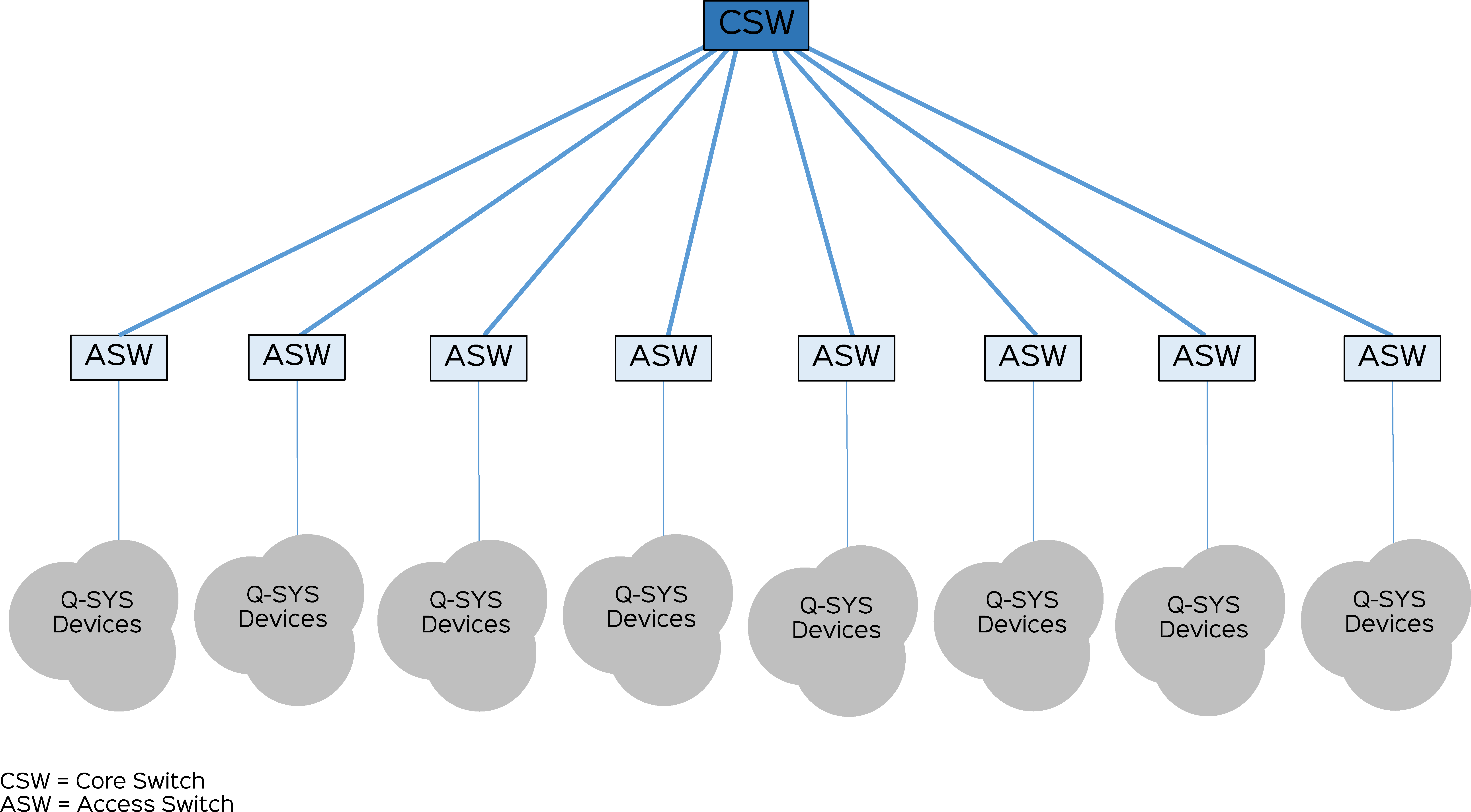
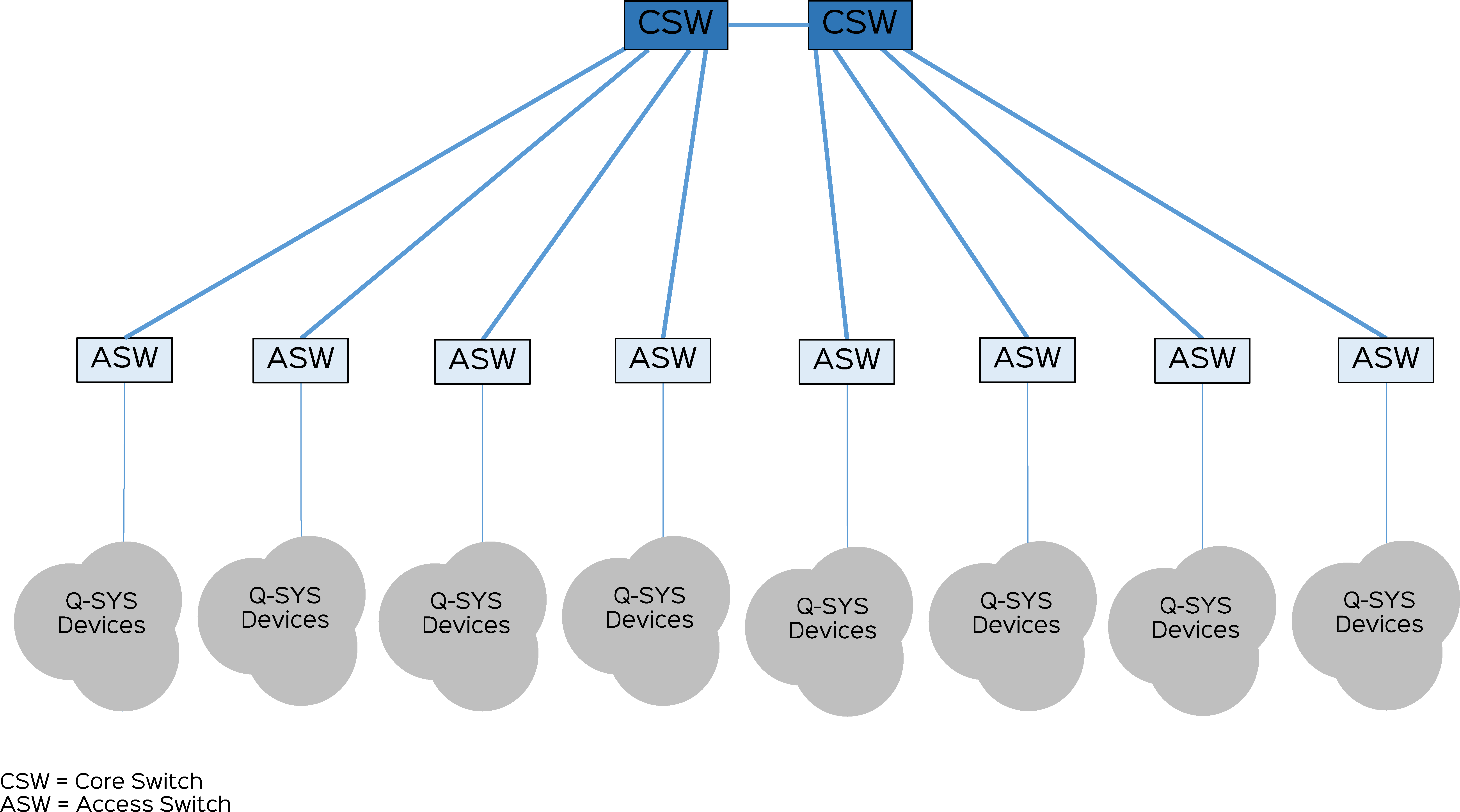
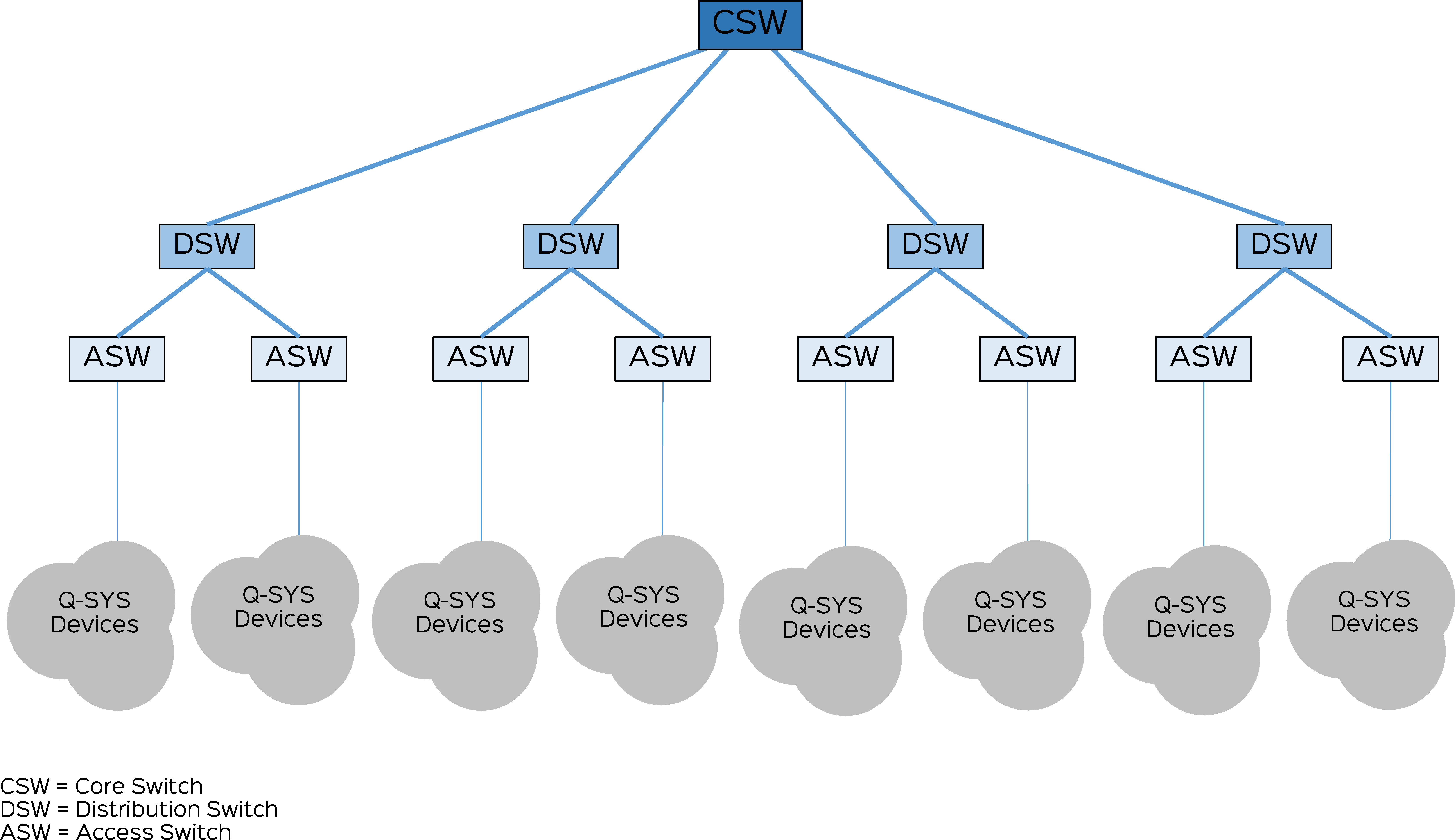
No more than 5 hops are allowed between any two points (3 or less is recommended) with up to 100 meters between switches. Hop count is defined as how many switches there are between two system nodes. Network diameter is the measurement between the two nodes with the longest physical path in the network. When possible, position the Q-SYS Cores towards the center of the network to minimize switch hop count.
Note: You can use 10 Gigabit in place of 1 Gigabit while following the 1 Gigabit design rules.
Since all Q-SYS equipment is 1000BASE-T, the diameter of a 1-hop network is limited to 200 meters by the two 100 meter 1000BASE-T CAT-5e cables leading into the single Ethernet switch in a 1-hop scenario.
The maximum allowed diameter for a 2-hop network is 35 kilometers.
The longest path in a 3-hop core-switch configuration can be no longer than 29 kilometers.
Tip: If performance issues are observed, consider connecting Q-SYS Core processors to the core switch of the network.
The longest path in a 4-hop core-switch configuration can be no longer than 22 kilometers.
Tip: If performance issues are observed, consider connecting Q-SYS Core processors to the core switch of the network.
The maximum allowed diameter for a 5-hop network is 15 kilometers.
Tip: If performance issues are observed, consider connecting Q-SYS Core processors to the core switch of the network.
Audio Streams
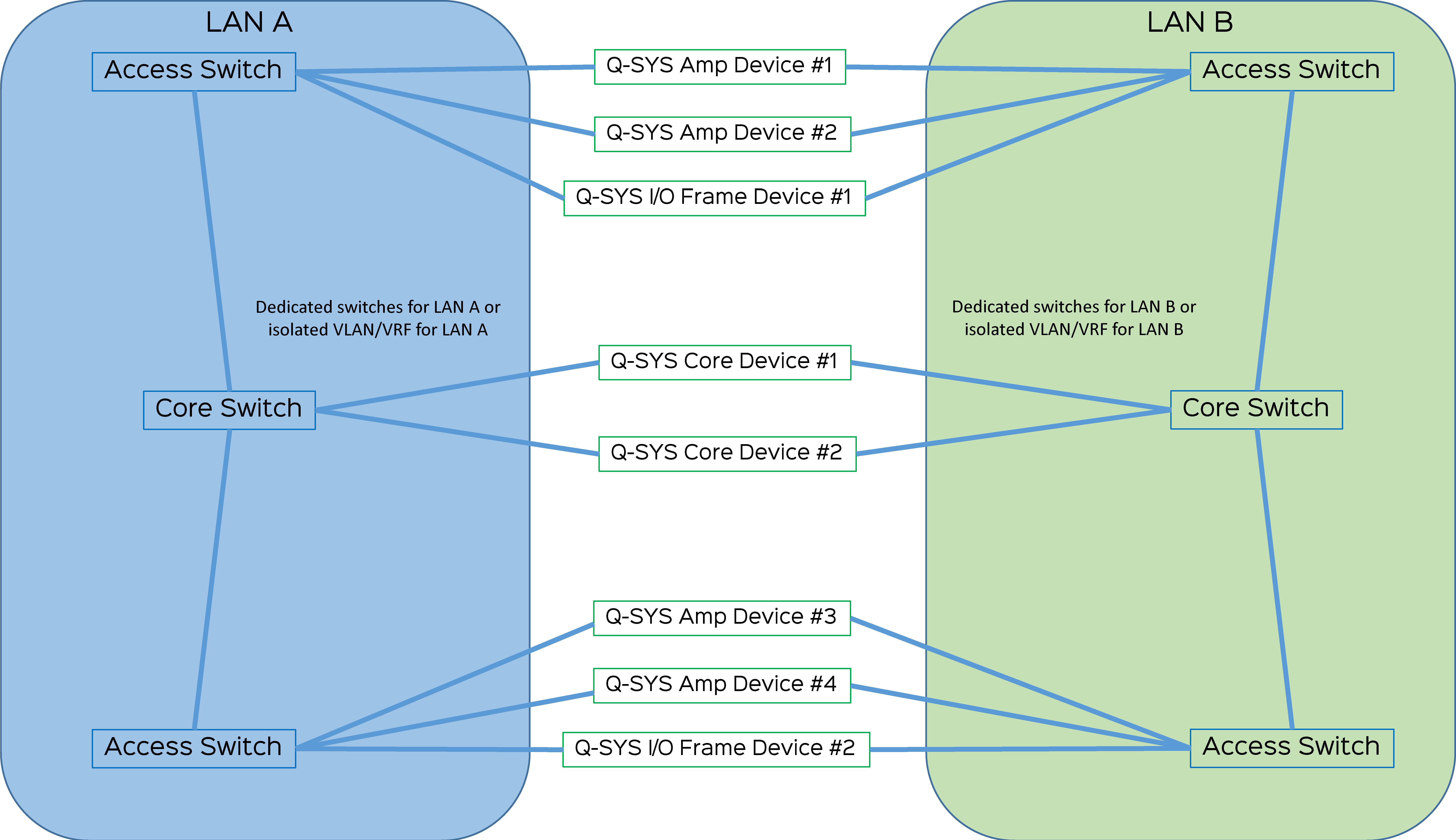
- 1-Gigabit backbone bandwidth for systems not utilizing audio stream redundancy (i.e., no LAN B connections).
- 1-Gigabit backbone bandwidth on each network for installations using separate networks for redundancy.
- 2-Gigabit backbone bandwidth required for installations using redundant connections to a single audio network.
Video Streams
Refer to the Clocking, Audio, Video, & Control topic for bandwidth and Inter-Switch Link (ISL) considerations for NV-32-H network AV streams.
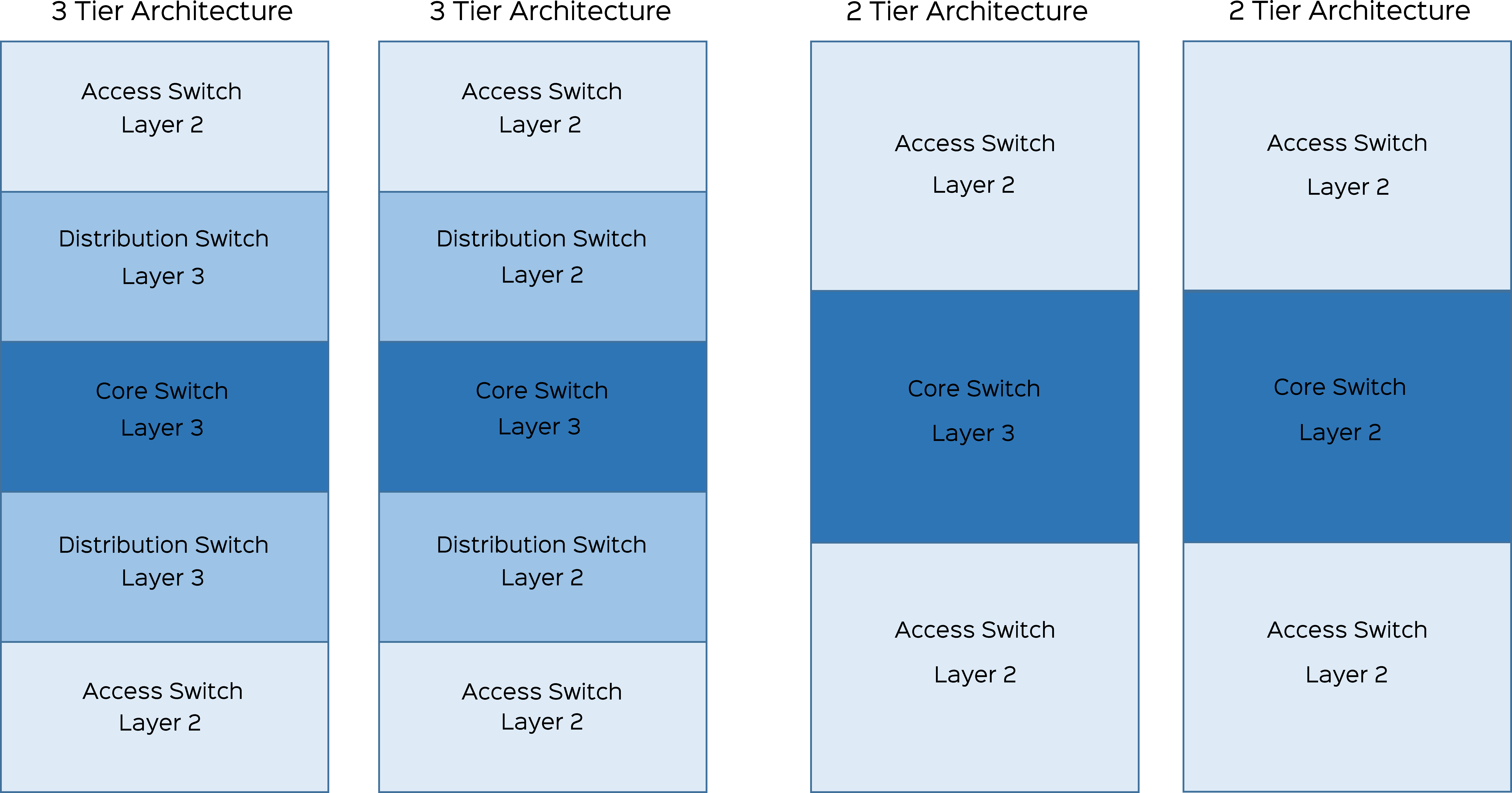
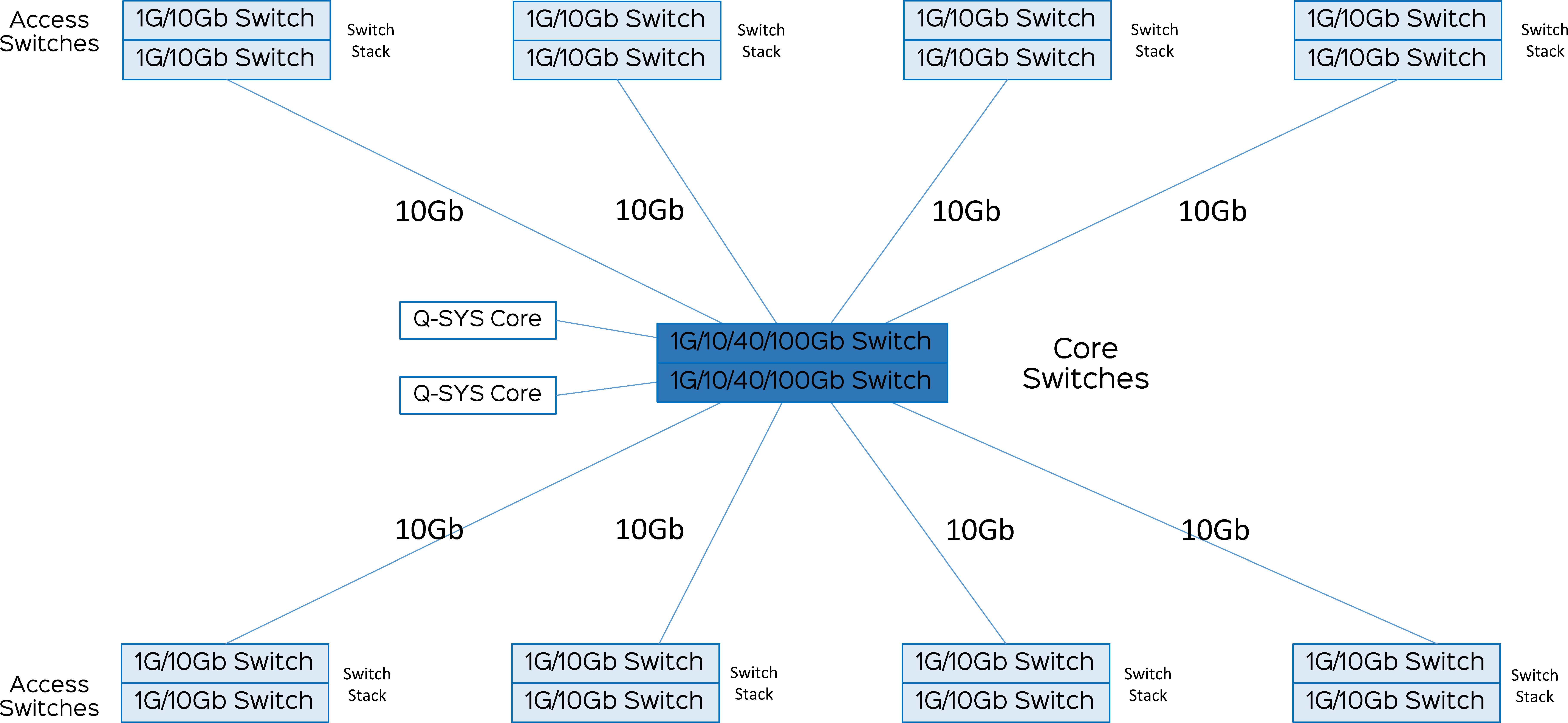
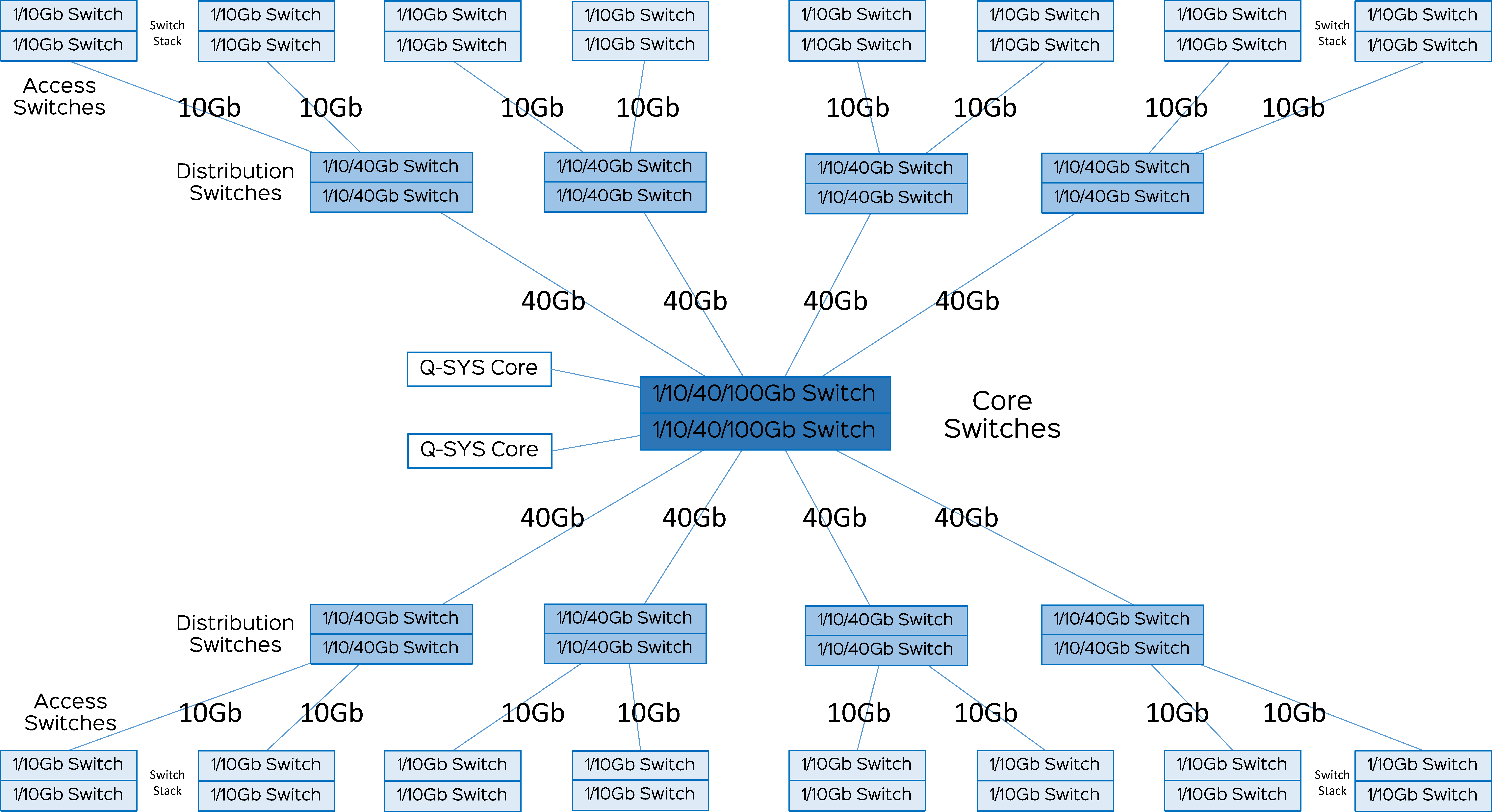
These diagrams show examples of two tier and three tier switch architectures. The switch stack assumes a true back plane interconnect that typically is measured in the nanoseconds delay domain with no packet loss and very high bandwidth capacity. When possible, position the Q-SYS Cores towards the center of the network to minimize switch hop count.
