GPIO Out (Core 8 Flex, I/O-8 Flex )
The General Purpose Input/Output (GPIO) connections allow the Q-SYS network to interface with miscellaneous outside devices, such as LED indicators, switches, relays, and potentiometers, and with custom or third-party controls. Using the GPIO Out you can control external hardware.
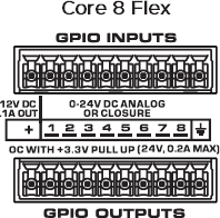
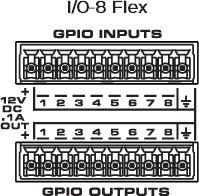
The GPIO pins in Q-SYS Designer are representative of the pins on the color-coded (typically black) Euro-style connector on the rear panel of the device. The numbers stamped on the rear panel relate to the GPIO pins in Q-SYS Designer. The first and last pins are not numbered as they are not GPIO pins but a DC reference voltage and ground, respectively.
Note: Refer to the Using GPIO Inputs and Outputs technical note on the QSC website to learn more about the I/O-8 Flex GPIO.
The GPIO allotment on the Core 8 Flex and I/O-8 Flex totals eight inputs and eight outputs. Configure each independent input and output in the Properties pane.
Flanking each row of eight GPIO inputs and outputs is a +12V DC terminal and a ground or reference terminal that can be used for potentiometers (input), relay coils and LEDs (output), and other uses. The +12V pins use a self-resetting fuse and each has up to 100 mA available.


Tip: For additional properties not listed, refer to the Properties Panel help topic for more information.
GPIO 1-8
Type
Select one of the following for each of the 8 GPIO pins that you use.
- Digital Output (TTL 3.3V) – 3.3VDC is supplied to the GPIO Output pin when the Output button is On.
- Open Collector (24V, 200mA Max), with Pullup to 3.3V
- Raw – The Raw mode is for advanced capabilities. If there is something you cannot do in the standard choices, contact QSC Support for detailed information. Note that when you select Raw as the direction, there are two instances of that pin on the GPIO component; one input, and one output.
Output
This button supplies a 0 in the Off position and a 1 (3.3V TTL) in the On position.
Invert
Available when the Properties > Type is Raw. The Raw mode is for advanced capabilities. If there is something you cannot do in the standard choices, contact QSC Support for detailed information.
The Control Pins that show, depend on the type of GPIO in use. You must select the Type (Raw) to make this Control Pins accessible.
|
Pin Name |
Value |
String |
Position |
Pins Available |
|---|---|---|---|---|
|
Output |
0 1 |
false true |
0 1 |
Input |
|
Invert |
0 1 |
false true |
0 1 |
Input / Output |
Q-SYS device GPIO output states are undefined during boot-up and design redeploy. In the following table, "While On" and "While Off" indicate the button setting as defined in the running design file. During a reboot or redeploy, the setting may toggle depending on the GPIO type before returning to the defined setting after the design starts running.
Bold text indicates a temporary GPIO setting during boot-up and redeploy.
Core 8 Flex and I/O-8 Flex GPIO
Note: The Core 8 Flex and I/O-8 Flex GPIO output position persists during boot-up and redeploy.
|
GPIO Type |
While On |
While Off |
|---|---|---|
|
Digital Output |
Stays On |
Stays Off |
|
Open Collector |
Stays On |
Stays Off |
|
Raw |
Stays On |
Stays Off |
