GPIO Out (QIO-GP8x8)
The QIO-GP8x8 includes eight General Purpose Output pins for extension of Q-SYS Control to third-party devices. In the Q-SYS Designer Software component properties, you can configure the output signal type for each pin – digital, open collector, or raw.
The GPIO Out component represents the GPIO OUTPUT connection pins on the rear of the QIO-GP8x8. Use one of the included 10-position Euro connectors.
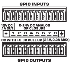
+12V
12V DC, 0.1A output.
1-8
Eight outputs, user-configurable in the component Properties. Pins 1-8 are the equivalent of pins 1-8 in the Q-SYS Designer Software GPIO Out component.
Ground
Signal ground reference for GPIO output connections.
Control Pins represent the Controls available in the component's Control Panel. Control Pins are used to link controls between Schematic Elements, and link to/from Control Scripts. Control Pin signal pins are represented by a () square, and the wiring is represented by a thick blue/white line.
QIO GPIO Out Properties
Name
The Name may contain ASCII letters 'a' through 'z' (case-insensitive), the digits '0' through '9', and the hyphen. Names cannot begin or end with a hyphen. No other symbols, punctuation characters, or blank spaces are permitted.
Note: This name must match the Hostname for the device as defined in Core Manager or Peripheral Manager.
Location
User-defined name that groups the component with other components in the same physical location – for example, "Rack 1" – or in the same organizational scheme.
Is Required
When enabled, and the device is not found on the network, the device is reported as 'Missing', which is an error condition. This is the default behavior. When disabled, and the device is not found on the network, the device is reported as 'Not Present', which is not an error condition.
Dynamically Paired
Indicates that this virtual component can be paired with the same type of hardware without changing the network ID of the hardware or the name of this component. Refer to the Q-SYS Core Manager Dynamic Pairing topic for more information. The default is 'No'.
GPIO-1 to 8
Type
Select the type of GPIO output:
- Digital Output (TTL 3.3V): 3.3VDC is supplied to the GPIO output pin when the Output control is enabled.
- Open Collector (200mA): 24V, 200mA max with pull-up to +3.3V.
- Raw: This mode is for advanced capabilities. If there is something you cannot do using the other choices, contact Q-SYS Support for assistance.
Graphic Properties
Label
Use the Label property to change the name of the component in the schematic. The Label property defaults to the component name. To learn more about renaming schematic elements, see Organizing Your Design.
Position
The coordinates reference a specific place in the schematic - for example,"100,100" (horizontal, vertical). 0,0 is the upper left corner of the schematic.
Fill
Sets the fill color of the component in the schematic.
Script Access Properties
Code Name
Displays the currently assign name for control access. You can use the auto-assigned name or customize it. Q-SYS will automatically check all Code Names in the design to ensure name is unique.
Script Access
Defines whether the component will be accessible by script and/or externally, or not at all. Choices include All, External, None (default), and Script.
- None (default) - Not accessible by any script, plugin, or by Q-SYS Remote Control Protocol (QRC).
- Script - Can be accessed by scripts, such as Text Controller, Block Controllers, and plugins only.
- External - Can only be accessed by 3rd party controls systems using component commands from the Q-SYS Remote Control Protocol (QRC).
- All - No restrictions, can be accessed by 3rd party control systems via Q-SYS Remote Control Protocol (QRC), or script objects or plugin objects.
Tip: Use Script Programmer Mode to quickly view the Script Access setting directly on the component in the design schematic without the need to disconnect from the Q-SYS Core processor.
Output
This button sends a 0 in the Off position and a 1 (3.3V TTL) in the On position.
Invert
This button is available when the Type is Raw.
Pin Name |
Value |
String |
Position |
Pins Available |
---|---|---|---|---|
Output (Digital Output, Open Collector, Raw) |
0 1 |
false true |
0 1 |
Input |
Invert1 |
0 1 |
false true |
0 1 |
Input / Output |
1. Available in the Control Pins list when Type is set to Raw. |
Q-SYS device GPIO output states are undefined during boot-up and design redeploy. In the following table, "While On" and "While Off" indicate the button setting as defined in the running design file. During a reboot or redeploy, the setting may toggle depending on the GPIO type before returning to the defined setting after the design starts running.
Bold text indicates a temporary GPIO setting during boot-up and redeploy.
QIO-GP8x8 GPIO
GPIO Type |
While On |
While Off |
---|---|---|
Digital Output |
Stays On |
Toggles to On |
Open Collector |
Toggles to Off |
Stays Off |
Raw |
Stays On |
Toggles to On |