Mic In (NM-T1)
Use the Mic In component to configure an NM-T1's microphone beams, noise reduction, and Acoustic Echo Cancellation (AEC) parameters. The component accepts reference audio from Far-End audio sources (for integrated AEC processing) and sends the microphone's audio signal to Q-SYS audio processing components and audio outputs.
Tip: Because the NM-T1 Mic In component includes integrated AEC processing, no additional AEC configuration with a separate Acoustic Echo Canceler component is needed.
Note: The NM-T1 is supported in Q-SYS 9.7.0 and later.
Input Pins
Reference
This pin receives a single incoming audio signal from a Far-End audio source, such as a Speakerphone In component (USB Audio Bridge), VoIP In (Softphone), or POTS In component. The Reference is then used for AEC processing directly within the Mic In component.
Output Pins
Conference 1-4
These four pins correspond to the four microphone beams on an NM-T1. Connect these to audio processing components (equalizers, mixers, etc.) and finally to an audio output, such as Speakerphone Out, VoIP Out, or POTS Out, depending on the conferencing solution within the design.
Reinforcement 1-4
Optional. If enabled in Properties, these pins output to the Near-End conference room loudspeakers.
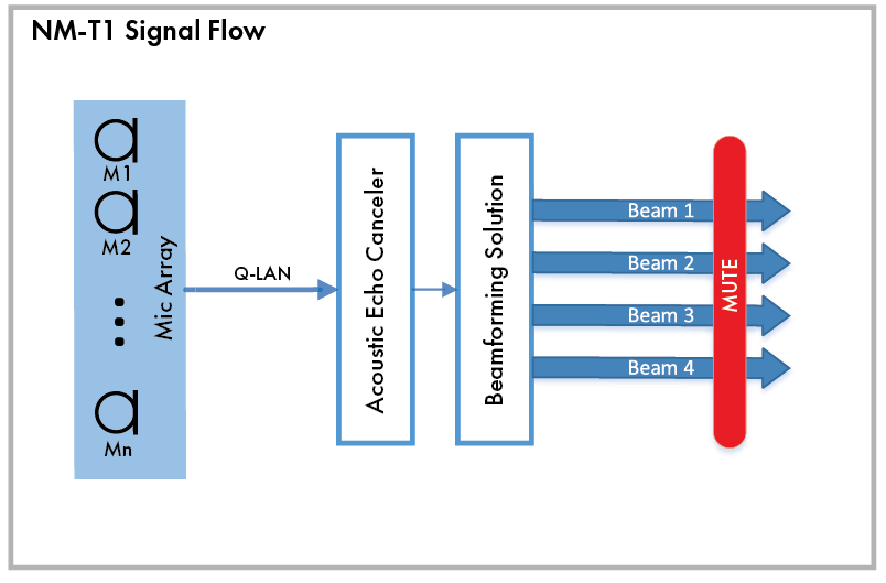
Audio signals captured by the NM-T1 mic array are sent on the Q-LAN network to the Acoustic Echo Canceler (within the Mic In component), which are then formed into beams. Muting occurs across all four beams simultaneously.
Tip: Muting is applied post-AEC to minimize re-convergence time.

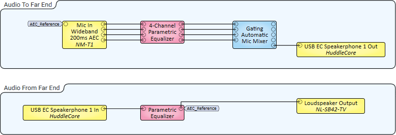
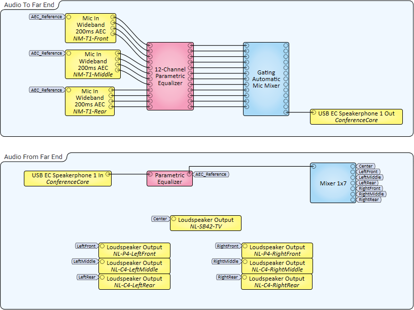
These examples demonstrate audio signaling from one NM-T1 microphone (Small Room) and multiple NM-T1 microphones (Large Room). Though these examples show USB Audio Bridge - Speakerphone In and Out components to receive and send audio from and to the far end, another conferencing audio solution could be used as well, including Softphone (VoIP In and Out) and POTS In and Out.
In this example, a single NM-T1 microphone is used to capture four audio zones (beams) within a smaller collaboration space, such as a huddle room. Each beam output is equalized and then sent to a Gating Automatic Mic Mixer to generate a single mixed audio channel that is in turn sent to a USB-connected, software-based conferencing codec via a Q-SYS Core processor's USB Audio Bridge. Audio received from the far end is output to an NL-SB42 network PoE soundbar mounted under a display in the room.

In this example, three NM-T1 microphones are placed on a table in a larger collaboration space, such as a conference room. Similar to the Small Room example, beam outputs – this time from all three mics – are equalized, mixed, and output to USB-connected conferencing software. Because this is a large room, it contains multiple NL Series Network Loudspeakers for output of Far-End audio.

Tip: For additional properties not listed, refer to the Properties Panel help topic for more information.
NM-T1 Properties
Bandwidth
This property controls the audio bandwidth of the microphone.
- In Wideband mode (default) the sample rate is 16 kHz and optimized for processing efficiency and capturing speech.
- In Fullband mode, the sample rate is 48 kHz and is optimized for applications that benefit from full bandwidth audio capture and playback, such as those requiring voice lift.
Note: The specified Bandwidth mode affects the maximum number of NM-T1 microphones and third-party microphone AEC processing you can have in a design, as well as the available input Network Audio Channels for the design's Q-SYS Core processor model. For details, see NM-T1 Quantity and AEC Channel Limits.
Beam Orientation
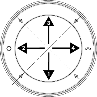
This property allows the designer to adjust the orientation of the four microphone beams relative to the physical mic/mute buttons on the NM-T1, either Centered on Mic Buttons (default) or In Between Mic Buttons.
Max Noise Reduction
This property sets the maximum attenuation of the Noise Reduction processing: 10dB (default), 20dB, or 30dB.
AEC Tail Length
Tail length is the maximum room impulse response that the adaptive filter can model, from 100ms to 400ms. Typically, you would use 200ms (default), but for exceptionally reverberant rooms, you may want to use 400ms.
Reinforcement Outputs
Select Yes to make the Reinforcement output pins available, or No (default) to hide them. When enabled, connect the Reinforcement pins to the Near-End conference room loudspeakers.
Beam
Mute
Press to mute all beam inputs. Refer to the Signal Flow section for more information.
Peak Input Level (dBFS)
Measures the peak digital audio signal input to the microphone, from -120 to 20 dB.
Beam ID
Press to activate the corresponding beam quadrant on the NM-T1 LED ring to validate microphone placement and Beam Orientation.
Beam Enable
Press to enable (default) or disable the corresponding NM-T1 microphone beam.
Gain
Use the Gain control to adjust the microphone gain level, from -100 to 20 dB.
Tip: Increasing the gain level can be useful if the source signal is especially low.
Post-Processor
Noise Reduction (NR)
Noise Reduction reduces the level of relatively steady state noises like fans, lawn mowers, wind, and mains electrical hum. The goal is to reduce these noises without affecting the desired speech. This control determines how much, between 0 and 10 dB, these steady-state noises are reduced. The more you increase the value, the more aggressively the noise is removed at the expense of distorting the Near-End microphone signal. The default value is 6.00 dB.
NR Enable
Enables (default) or disables the noise reduction functionality of the AEC.
Canceler
Low Ref Adapt Hold
The Low Reference Level Adapter Filter Hold indicator corresponds to the Adaptive Filter > Hold If Ref Level Below control, and turns on whenever the reference level falls below the threshold level. This means that the adaptive filter is no longer being updated.
Echo Return Loss Enhancement (ERLE)
This meter indicates how much, in dB, the Far-End echo arriving at the Near-End microphone is attenuated by the AEC adaptive filter once the filter has converged. The ERLE meter is used to indicate how effective the AEC is in terms of suppressing the acoustic echo. A reading below 10 dB during Far-End only talk may indicate that the room tail is longer than the AEC tail property. Readings above 20 dB during Far-End only talk indicate that the AEC is working properly.
Bypass
Bypasses the AEC function, including its latency, when activated. Bypass is off by default.
Reference-to-Microphone Level Ratio (RMLR)
This meter indicates how much dB, between -10 and 10, the Far-End reference signal level exceeds the Near-End microphone signal level. Use the RMLR meter to adjust the reference signal level during Far-End only talk. In general, the Far-End reference signal level should approximately equal the Near-End microphone signal level, as indicated by a ratio of 0dB. The ratio can be adjusted using the Reference Gain knob.
Target 0dB
Adjust the Reference Gain until the RMLR is at the target of 0dB.
Reference Gain
This knob adjusts, in dB between -40 and 0, the Far-End reference signal level. The default is 0. In general, the Far-End reference signal level should approximately equal the Near-End microphone signal level, as indicated by 0dB on the Reference-to-Microphone Level Ratio meter.
Adaptive Filter
Hold If Ref Level Below
Sets the threshold, in dB between -100 and 0, below which the AEC adaptation stops. The default is -100dB. In most cases, the Far-End reference signal is clean and of sufficiently high level, so this level should be left at the default. However, if the Far-End reference signal has elevated background noise, this noise can cause issues with AEC adaptation. In this case, try adjusting the Hold level to just above the Far-End background noise level.
Post-Processor
Residual Echo Suppression (RES)
Residual Echo Suppression applies additional suppression, between 0 and 100%, to any residual echo that was not removed by the adaptive filter and echo reduction functions of the AEC component. The default is 25.0%. The more you turn it up, the more aggressively the residual echo is suppressed at the expense of distorting the Near-End microphone signal.
RES Enable
Enables or disables Residual Echo Suppression functionality of the AEC. RES is enabled by default.
| Pin Name | Value | String | Position | Pins Available |
|---|---|---|---|---|
|
Beam 1-4 |
||||
|
Enable |
0 1 |
disabled enabled |
0 1 |
Input / Output |
|
Gain |
-100 to 20 |
-100dB to 20dB |
0 to 1.00 |
Input / Output |
|
Identification |
0 1 |
false true |
0 1 |
Input / Output |
|
Peak Level |
-120 to 20 |
-120dB to 20dB |
0 to 1.00 |
Output |
|
Bypass |
0 1 |
no bypassed |
0 1 |
Input / Output |
|
Echo Return Loss Enhancement |
0 to 20 | 0dB to 20dB |
0 1 |
Output |
|
Hold If Reference Level Below |
-100 to 0 |
-100dB to 0dB |
0 to 1.00 |
Input / Output |
|
Low Reference Level Filter Adaptation Hold |
0 1 |
no yes |
0 1 |
Output |
|
Mute State |
0 1 |
false true |
0 1 |
Output |
|
Noise Reduction |
0 to 10.0 |
0dB to 10.0dB |
0.00 to 1.00 |
Input / Output |
|
Noise Reduction Enable |
0 1 |
disabled enabled |
0 1 |
Input / Output |
|
Reference Gain |
-40 to 0 |
-40dB to 0dB |
0.00 to 1.00 |
Input / Output |
|
Reference-to-Microphone Level Ratio |
-10 to 10 |
-10 dB to 10 dB |
0 1 |
Output |
|
Residual Echo Suppression |
0 to 100 |
0% to 100% |
0.00 to 1.00 |
Input / Output |
|
Residual Echo Suppression Enable |
0 1 |
disabled enabled |
0 1 |
Input / Output |


