GPIO In (NV-32-H)
The NV-32-H includes two General Purpose Input pins for extension of Q-SYS Control to third-party devices. In the Q-SYS Designer component properties, you can configure the input signal type for each pin – contact closure, digital, analog, potentiometer, or raw.
The GPIO In component represents the GPIO IN connection pins on the rear of the NV-32-H. Use one of the included 5-pin Euro connectors.
Note: The RS-232 and GPIO IN pins share a 5-pin Euro connector. You can use both connection types simultaneously.
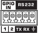
1, 2
Two inputs, 0-24 V analog input or contact closure. Pins 1-2 are the equivalent of pins 1-2 in the Q-SYS Designer GPIO In component.
Ground
Earth ground reference for GPIO input and RS-232 connections.
This component does not have standard input and output pins. See Control Pins.
Core Properties
Note: See the HDMI I/O (NV-32-H) topic for other NV-32-H properties.
GPIO-1, 2 Type
Select the type of GPIO input:
- Digital Input (TTL 3.3V)
- Contact Closure Input
- Potentiometer (10k Ohm, 12V)
- Potentiometer (2-wire)
- Analog Input (0-24V, low z)
- Raw
USB Bridging – Common Properties
These properties appear based on the USB bridging capabilities of the Q-SYS device. Refer to the USB Video Bridge and USB Audio Bridge topics to see what Q-SYS Core processors and peripherals support USB bridging.
USB Bridge Name
User-defined name given to the USB Bridge, from 1 to 24 characters. The Name may contain ASCII letters 'a' through 'z' (case-insensitive), the digits '0' through '9', and the hyphen. Names cannot begin or end with a hyphen. No other symbols, punctuation characters, or blank spaces are permitted.
Zoom Compatibility
If you are using the HID Conferencing component to control a remote computer running Zoom, set this property to 'Enabled.' Otherwise, when controlling another conferencing app such as Skype for Business, set to 'Disabled' (default). When this property is enabled, the USB Bridge Name property is disabled, and the USB Bridge automatically uses the name of the device for compatibility with Zoom's allowed device list – for example, "Q-SYS Core 110f" or "Q-SYS NV-32-H".
Tip: Enabling Zoom Compatibility may improve the user experience with macOS conferencing solutions.
USB Video Bridge
Enable the USB Video Bridge to bridge Q-SYS Mediacast streams to USB, enabling you to view Mediacast video on a connected computer. This exposes the USB Video Bridge component in the I/O-USB Bridge Inventory tree. To see what Properties are available when the USB Video Bridge is enabled, see USB Video Bridge.
USB Audio Bridge
Provides the capability of passing audio via USB. When this is set to anything except 'Disabled', you can drag the Speakerphone and/or Sound Card components from the device's Inventory tree into your design. To see what Properties are available when the USB Audio Bridge is enabled, see USB Audio Bridge.
- Disabled: (Default)
- Speakerphone (1 x 1): Provides a speakerphone with an input and output component, each having 1 audio connection.
- Sound Card (2 x 2): Provides a sound card with an input and output component, each having two (stereo) audio connections.
- Speakerphone and Sound Card: Provides one speakerphone and one sound card with the same capabilities as described above.
- Advanced – If supported, allows up to any combination of four speakerphone / sound cards.
Speakerphone Mode
This selection is available only when Speakerphone or Speakerphone and Sound Card is selected in the USB Audio Bridge property. Indicates if the Q-SYS design has Echo Canceling (EC) or Non-Echo Canceling (NEC). This information is provided to the PC or Mac operating system so it can determine whether or not to use its own echo canceling.
Graphic Properties
Label
Use the Label property to change the name of the component in the schematic. The Label property defaults to the component name. To learn more about renaming schematic elements, see Organizing Your Design.
Position
The coordinates reference a specific place in the schematic - for example,"100,100" (horizontal, vertical). 0,0 is the upper left corner of the schematic.
Fill
Sets the fill color of the component in the schematic.
Script Access Properties
Code Name
Displays the currently assign name for control access. You can use the auto-assigned name or customize it. Q-SYS will automatically check all Code Names in the design to ensure name is unique.
Script Access
Defines whether the component will be accessible by script and/or externally, or not at all. Choices include All, External, None (default), and Script.
- None (default) - Not accessible by any script, plugin, or by Q-SYS Remote Control Protocol (QRC).
- Script - Can be accessed by scripts, such as Text Controller, Block Controllers, and plugins only.
- External - Can only be accessed by 3rd party controls systems using component commands from the Q-SYS Remote Control Protocol (QRC).
- All - No restrictions, can be accessed by 3rd party control systems via Q-SYS Remote Control Protocol (QRC), or script objects or plugin objects.
Tip: Use Script Programmer Mode to quickly view the Script Access setting directly on the component in the design schematic without the need to disconnect from the Q-SYS Core processor.
Digital Input
This LED illuminates when there is a digital input present on a GPIO pin. Supported Types:
- Digital Input (+3.3VDC)
- Contact Closure – When this Type is selected, the pin has approximately 9 to 10VDC present when the contact is open (or nothing is connected) and the LED is off. When the contact is closed (pin is shorted to ground), the LED is on.
- Raw
Analog Input
The analog input knob appears for these Types:
- Analog – allows a low impedance, 0 – 24VDC signal input
- Raw
Both input voltages are displayed on a read-only knob control.
Potentiometer: Min Position, Calibrate Min, Max Position, Calibrate Max
The Potentiometer knob follows the position of the physical potentiometer connected to the GPIO pin. To calibrate Q-SYS to the potentiometer:
- Turn the physical potentiometer to its minimum position.
- Click the Calibrate Min button. A value displays in the Min Position field.
- Turn the physical potentiometer to its maximum position.
- Click the Calibrate Max button. A value displays in the Max Position field.
If you know the values for Min Position or Max Position, you can enter them manually.
Pullup Enable
When enabled, provides a 5.11K pull-up resistor to +12VDC on the input pin when the Type is Raw.
Pin Name |
Value |
String |
Position |
Pins Available |
---|---|---|---|---|
Digital Input |
0 1 |
false true |
0 1 |
Output |
Contact Closure |
0 1 |
false true |
0 1 |
Output |
Potentiometer Position |
0 to 1.00 |
0 to 1.00 |
0 to 1.00 |
Output |
Calibrate Maximum1 |
0 1 |
false true |
0 1 |
Input |
Calibrate Minimum1 |
0 1 |
false true |
0 1 |
Input |
Maximum Position1 |
0 to 1.00 |
0 to 1.00 |
0 to 1.00 |
Input / Output |
Minimum Position1 |
0 to 1.00 |
0 to 1.00 |
0 to 1.00 |
Input / Output |
Analog Input |
0 to 24 |
nn.nnnV |
0 to 1.00 |
Output |
Raw |
||||
Analog Input |
0 to 24 |
nn.nnnV |
0 to 1.00 |
Output |
Digital Input |
0 1 |
false true |
0 1 |
Output |
Pullup Enable2 |
0 1 |
false true |
0 1 |
Input |
1. Available in the Control Pins list when Type is set to Potentiometer.2. Available in the Control Pins list when Type is set to Raw. |