Schematic Elements
A Schematic Element is anything that is in a Q-SYS Designer schematic. This can include Components, graphics including graphics/pictures from other applications, and text. This topic describes the various things that can be added to a Schematic, and how to use the common features of the Schematic Elements, and of Q-SYS as it relates to Schematic Elements.
The Design Elements are a list of the Inventory items you have added to your design, the Schematic Elements are a list of the Components you can add to your design, and the Properties pane lists the parameters you can specify when an element is in the schematic and selected.
Each of these three can be docked to top, bottom, and either side of the schematic. In addition, you can merge the three and the titles become tabs for selecting which you want to use. Click the title area and drag to the position you wish. When you start to drag one of the three, docking icons display; these are used to automatically dock the list when you move the cursor over one of the icons.
Right-clicking one of the title areas gives you various choices depending on whether the list is docked or floating.
Components are found in the Schematic Library, Inventory, and Snapshots. For the most part, the descriptions found here apply to all components. For details about a specific Component, refer to the individual topic. In the Schematic Library, Components are grouped into Audio Components, Control Components, and Layout type Components. In the Inventory section Components are under the individual Inventory item when it is added to the Inventory, Snapshots are in the Snapshot section under the Global Snapshot, and any Snapshots you add.

The upper section of the component has audio inputs on the left and audio outputs on the right. The type of connector pin depends on the type of the Component, and not all Components have both or any inputs and outputs. The Components found in the Inventory section can have digital and/or analog audio connectors. The Components in the Schematic Library have only digital audio connections. Refer to Connection Types for detailed information.
The lower section contains the Control Pins. Control Pins display on most components only after you have selected them in the Properties > Control Pins section of the Component. Some Components only have Control Pins.
HoverMon
HoverMon enables you to hover over a digital input/output, audio or control pin, on a component and get information about the input or output of that pin. In addition, for audio pins, you can get audio output to your PC. The HoverMon does not work with analog inputs/outputs such as the output of a DataPort Out card. HoverMon is not available for pins that have no pertinent information to display. For example, momentary and trigger type buttons.
See Preferences for information about configuring HoverMon audio.
Design Mode
In the Design Mode, for both audio and control pins, HoverMon displays only the pin name and designation.

Emulate Mode
In the Emulate Mode, you can see the pin name, designation and, for the Control Pins, you can see the state or value of the control for that pin.

Run Mode
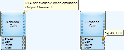
In Run mode, when you move the mouse over an audio connection it is identified in the hover text along with a graphical Real Time Analyzer (RTA - Band-Pass) spectrum describing the input or output of that pin. In addition, you have access to the controls for turning on audio to your PC's sound card, and "pinning" the HoverMon on that pin. Hovering over a Control Pin gives you "live" information about that control signal, for example, time, level, etc. You cannot "pin" the HoverMon to a Control Pin.

- In the example on the left, the HoverMon audio is turned off, and the HoverMon display is not pinned. When the HoverMon is not pinned you can move from one pin to another with your mouse.
- In the example in the middle, the HoverMon audio is on, audio is sent to your PC's audio card The HoverMon is also pinned; you can move your mouse, and the HoverMon stays open and continues to send the audio to your PC's audio card.
- In the example on the right, the HoverMon is over the Progress Control Pin. You can see the name of the pin, and its current value.
- See Configure Audio Monitor for information about configuring HoverMon.
Properties
When you place a component in the Schematic and select it, the component's Properties display below the Schematic Library in the right side pane. Some Properties dynamically control the values of other Properties and are documented for each Schematic Element.
- The Fill color is the color of the Schematic Element you currently have selected. You can change the color by clicking the Fill color selecting a new one, or by clicking the eyedropper tool to copy the color from something in the Schematic. This is helpful for grouping elements in your Schematic.
- You may select multiple components of the same kind and change all of the Properties, including selecting Control Pins, of all the selected components at the same time. If the components have different settings for some of the Properties, the differences are noted by one of the following methods: the value is missing, the value is fuzzy looking, a checkbox is filled in instead of checked.
- If you select multiple components of different kinds, only the common Properties are displayed.
- You may change any of these Properties when in the Design mode. In Run/Emulate mode, component Properties are not available.
Control Panel
Each Component has controls available for use during the run and Emulate modes. When you double-click a Component in the Schematic, the control panel for that Component displays.
You cannot make adjustments in the design mode. In the Emulate mode, you can make control settings, test control logic like Web Panels and Control Scripts, but audio is not processed. In the run mode ( Load from Core & Connect..., and Save to Core & Run) all the functions of the system are operating.
Controls
Use controls to set the various parameters for a component. Refer to the Using Controls topic for complete details.
Components are added to the Schematic from the Schematic Library, Inventory, and Snapshots. When a component is in the Schematic, you can make connections between it and other components to use in your design, make initial adjustments to controls, and so on. To add anything to the Schematic, select it and hold the left mouse button and drag it into the Schematic. You can also copy and paste most elements when they are in the Schematic. You cannot add Components to User Control Interfaces.
Left-side Pane
You must add items to Inventory, and Snapshots before you can add them to the Schematic. The exception is the Core it is always in the Inventory, you cannot delete it, or add additional primary Cores. Each item in the Inventory has a child Component or Components associated with it. You can drag either the item itself, or its individual component(s) into the Schematic. If you drag an item with multiple components into the Schematic, all of its associated components are placed into the Schematic.
- Click the Inventory or Snapshots accordion bar.
- The procedures for adding items from these sections are different, follow the instructions in the appropriate section to add items to the Schematic.
- You cannot copy and paste a Core or I/O Frame. Copying and pasting items such as loudspeakers is an effective way to duplicate the configuration of an item - configure the item first, then copy and paste it as many times as you need to match your hardware.
- You cannot place Inventory items in a Channel Group component.
Right-side Pane
Schematic Library
The Components in the Schematic Library are virtual in nature — they do not represent physical equipment. Components in the Schematic Library are grouped by function and listed alphabetically within their functional areas. The main functional areas are Audio Components, Control Components and Layout Components.
- From the Schematic Library find and select the item you wish to add. You can either manually find the component you want, or enter a key word in the search field.
- When you have selected the item, you can simply drag it into the Schematic. You may add as many Components from the Schematic Library as you wish.
- You may also copy and paste elements in the Schematic.
Using Find (Ctrl+F) you can find items in one of two ways.
- Context - Controls that have been copied can be found from the copy or the original.
- Label - A label is any text in the Schematic except text and values returned by the system, usually in a text box. Find by Label locates items using any part of the text.
You can easily find specific item if it:
- is a component of an Inventory item,
- is a component of a Snapshot Bank,
- has one or more controls, or the entire component in a Snapshot Bank,
- has one or more controls in the Named Control list,
- has one or more controls in a User Control Interface (UCI),
- has one or more controls copied into the Schematic,
- is a label of a component, control or a shape made by any of the Graphic Tools. You cannot use the Find feature to locate text displayed as a result in a text box. or the settings of controls, and so on.
To Find a Schematic Element
- Select one of the following:
- an Inventory item in the Inventory pane,
- a control or component in a Snapshot Bank,
- a control in the Named Controls list,
- a control in a UCI,
- a control that has been copied into the Schematic.
- Press Ctrl+F. The Context Finder displays in the upper right corner of the Schematic.
- Click the link provided in the Context Finder. Q-SYS jumps to the associated component in the Schematic.
To Find Items from a Schematic Element
- Select one of the following:
- a component of an Inventory item,
- a control in control panel that exists in a Snapshot Bank,
- a control in control panel that exists in the Named Controls list,
- a control in control panel that exists in a UCI,
- a control in control panel that has been copied into the Schematic.
- Press Ctrl+F. The Context Finder displays in the upper right corner of the Schematic.
- Click the link (or one of the links) provided in the Context Finder. Q-SYS jumps to the associated component in the Schematic.
Note: When you select a control in a control panel, it may exist in several places. For example, one control can exist in any of the following: Named Controls, Snapshot Bank, UCI, the Schematic.
The following rules apply for selecting any Schematic Elements:
- You can select multiple Schematic Elements as long as they're on same Schematic Page.
- To select all the components on a Schematic Page, select main menu > Edit > Select All or press Ctrl+A. You can also use the surround method described below.
- To select a single Schematic Element, click the element. When the mouse cursor is in a position to select the Schematic Element, the cursor is changed to the move cursor.
- To select a single connector on a Schematic Element, click the connector.
- To select multiple Schematic Elements or connectors on elements:
- Hold the Ctrl key and click the Schematic Elements or connectors one at a time. You can hold the Ctrl key and select multiple elements with any of the following methods as well.
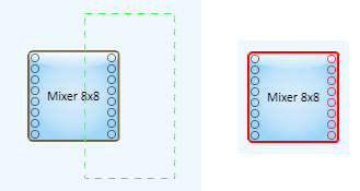
- Intersect - Click and hold the left mouse button and drag a box (dashed line) in a right-to-left direction to intersect the elements you wish to select. This method works well for selecting "wires". It also selects anything you may completely surround including connectors within elements.
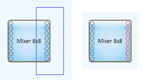
- Surround - Click and hold the left mouse button and drag a box in a left-to-right direction, to surround the elements you wish to select. This method works well for selecting multiple connectors or controls within elements, without selecting the element itself. If you use this method to select connectors with "wires" already connected, you will select the wires connected to the connectors as well. When both "wires" and connectors are selected, you can still drag the selected connectors to a different Schematic Element.
Note: If you want to select a of group pins, between the first and last pins, on the right side of a component, you can use the intersect method and select those pins. When you do this, the component is selected as well. Press and hold the Alt key, the selection box becomes a surround type box. Surround the pins you want to select, nothing else is selected. Another method is after selecting with a crossing box, press and hold the Ctrl key, then click the component. The component is no longer selected, but the pins remain selected.

Notice that the Mixer Component (right) is selected as well as the connectors. Contrast this to the example for the surround method.

- To deselect a Schematic Element, simply click another item, click in a blank area of the schematic, or press the Esc button.

Refer to the Signal Pins and Wiring in the Schematic topic for connection details.
Copying and pasting components is an effective way to create multiple instances of the same component with the same configuration. After you have added a component to the schematic and configured it, you can copy and paste it, and the pasted component keeps the configuration settings of the copied one. If you have made any control settings in either the Run or Emulate mode, when you copy and paste the component, the control settings are copied as well.
There are several convenient ways to copy and paste components in the schematic while in design mode.
Select the component then:
- Main menu > Edit > Copy, or press Ctrl+C. Select main menu > Edit > Paste, or press Ctrl+V, then move the mouse cursor to where you want to paste the component and click the left mouse button.
- Main menu > Edit > Ctrl+D (Duplicate) or just press Ctrl+D, then click the left mouse button where you want to paste the component.
- Press the Alt key, click and hold the left mouse button on the component(s), then drag the component(s) to a new location, when you release the mouse button, the components have been copied to the new location.
- Right-click the component to access a context menu. Options include Cut, Copy, Paste, Delete, and Duplicate.
There are a few items that cannot be copied or pasted. For example, the Core or I/O Frame and any of their sub-components. If you copy and past other inventory items a new item is added to your Inventory list each time you paste it - handy for adding multiple loudspeakers with the same configuration.
Copying and Pasting Controls
Design Mode
In the Design Mode you can copy controls from a Component's Control Panel and paste them in the Schematic or into a User Control Interface (UCI). The controls you paste are tied to the controls from which they were copied. This means you adjust one control, and the other control changes with it.
When you copy/paste controls into a UCI, the pasted controls are used by an end-user to manipulate the settings of the Component from outside Q-SYS Designer. You can arrange the desired controls in the UCI to better suit the needs of the end-user.
You can copy/paste controls into the Schematic to arrange them in other ways than they appear in the Component's Control Panel. This can be helpful when troubleshooting, or setting up and testing the Q-SYS installation.
You can copy the controls into a Popup Button window, then open and close the popup window to show or hide the controls.
If you place a button into the Schematic, UCI, or Popup Button window, you can drag a bitmap type graphic into the button and it will be sized to fit into the button. You can also copy an object (not a file) from a vector type graphic program into the Schematic, then drag it into the button.
- Open the Control Panel of a Component from which you wish to copy controls.
- Select the controls, text, and graphics you wish to copy. Use any of the methods of selecting as described in Selecting Schematic Elements.
- Copy and paste the controls using any of the methods described in Copying and Pasting Schematic Elements.
- Once a control is pasted into a UCI or Schematic, you can change the size of the control by selecting it and dragging one of its handles.
- If you change the size of a Fader or Meter, the orientation changes from vertical to horizontal at the point when the width of the control exceeds the height. The direction of the control is from left (low) to right (high). In the case of the Fader, you can select Reverse Action in the properties and change the direction of the control.
- If you copy a control into a Schematic or UCI, you can change it to a Text Field in the Properties for the control. In the emulate or run mode, you can drag the mouse over the text field and change the value based on the type of control it was originally. For example, if you drag a Combo Box into the Schematic and change it to a Text Field, then emulate, you can change to any of the originally available values in the same way you would change a Knob or Fader control - click and drag up or down.
- If you copy a control, then delete the component from which it came, the control is "orphaned". The control is changed to an orange color, and displays a question mark (?) over
Run or Emulate Mode
In the Run or Emulate mode, you can copy the settings of one or more controls from a Component's Control Panel, and paste them into another Component's Control Panel to duplicate the control settings. In addition, you can copy all controls without going into the components control panel.
Note: The Component you are copying to must be the same kind of Component as the one you are copying from.
To copy one or more control settings:
- Ensure the design is in the Run or Emulate mode.
- Open the Control Panel of the Component from which you wish to copy and the Control Panel of the one you are copying to.
- In the "copy from" Control Panel, select the controls with the settings you want to duplicate. You can select by:
- clicking a control
- pressing and holding the Ctrl key to select multiple controls
- pressing Ctrl+A to select all the controls in a Control Panel.
Tip: If the first control you select is a button, selecting it changes the state of the button. To avoid this, press the Ctrl key then select the control.
- In the Control Panel of the Component to which you are copying the control settings, select the same controls that you copied. Press Ctrl+V to paste the control settings.
- Ensure the design is in the Run or Emulate mode.
- Select the "copy from" component.
- Right-click and select the copy all from component icon - you can hover over the icons to find the right one.
- Select the 'copy to' component.
- Right-click and select the Paste All to Component icon - you can hover over the icons to find the right one.
- The settings are copied.
Note: The Property settings, time readouts, and so on, are not copied.
When you select a component in the schematic, you can move it using a few different methods.
- Select the component and hold the left mouse button then drag it to where you want it placed in the Schematic.
- While you are dragging it, snap-guides appear as a corner of the component aligns either vertically, horizontally or both, with another component in the Schematic. This helps you align the components in your schematic. To disable the snap-guides, press the Ctrl key after you begin moving the component.
- To constrain the movement of a component to either vertically or horizontally, press the Shift key after you begin moving the component.
- Select the component and enter the desired coordinates in the Position field, found in the Properties for that component.
- You can also select the component, press Ctrl+x (cut) then paste it (as explained above) in its new location, including different Schematic Pages.
Select the Schematic Elements you want to group, then press Ctrl+G (or Main menu >Tools >Group). The items can be moved, cut, copied, pasted, deleted as a group, without changing their relative position. To ungroup a set of grouped items, select the group, then press Ctrl+Shift+G.
Note: You can connect standard wiring between components in a group and components outside of a group. Wires and Pins are not part of the group so they will not be copied and pasted. This allows them to be selected and deleted.
Select the Schematic Element(s) you want to delete and press the Delete key. If there are any "wires" connected to an element, they are deleted as well. If the element is an item from the Asset Manager Panel, it is returned to the Asset Manager Panel and can be reused.
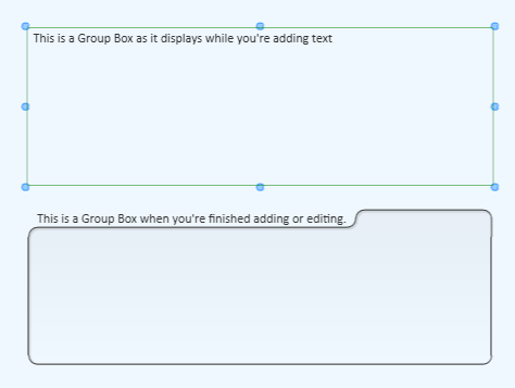
You can add Headers, Text Blocks, and Group Boxes to organize, annotate, and enhance the appearance of your design / User Control Interface using the following Graphic Tools. For complete information see Graphic Tools.
Header

Text Block

Group Box

Pasting Lists into Headers, Text Boxes, and Group Boxes
If you have a list of items, or a set of sequential numbers, you can select the list/sequence and paste it into a group of Headers, Text Blocks, or Group Boxes. The list or sequence must be either tab delimited, or on separate lines (carriage returns).
- In Q-SYS Designer, add the number of boxes you need to accommodate the list.
- Arrange the boxes in either a column or row. The resulting order, after pasting, is in the order of the list, either top to bottom or left to right.
- Select the list you wish to paste. The list can be in a word processor, a Q-SYS Text Block (not Header or Group Box), or other application that can produce a tab delimited list, or lines with carriage returns.
- In Q-SYS Designer, elect the group of boxes you wish to populate with your list.
- Paste the list using Ctrl+V or from the main menu, Edit > Paste.
Note: There are other methods of creating a list that can be pasted into Q-SYS boxes, and some that won't work. For example, you cannot paste a list from Microsoft Excel. However, if you copied the list from Excel into Microsoft Word, it becomes a table that you can paste into Q-SYS boxes. Other applications have not been tested.
