Open topic with navigation
System Description
Overview
Q-SYS is an Integrated System Platform that provides all the audio routing, processing control, and monitoring for a facility. Q-SYS is a centralized DSP, integrated-system audio solution. The DSP is centralized to allow faster development and deployment of new features, and requires fewer hardware changes as well. Q-SYS has been designed around four major criteria: Sonic Quality, Reliability, Power and Flexibility. All of the dedicated, networked components run with a customized Linux operating system.
Components
Q-SYS is comprised of the following dedicated components.
- Q-SYS Core - (required) The Core is Q-SYS' central processing unit. The Core processes and routes all audio, controls peripheral devices, manages firmware updates to the peripheral devices, using Q-LAN over a 1-gigabit Ethernet network with standard network interfaces. Cores 1000, 3000, 4000 each have one slot available to add one card. Cores 250i, and 500i, each have eight slots for I/O cards. Refer to the Q-SYS I/O Frame for a list of I/O cards.
For more detailed information on networking, refer to Q-LAN Networking.
|
Core 110f
|
128
|
128
|
N/A
|
|
Core 250i
|
64 divided between In and Out
|
1024
|
|
Core 500i
|
128 divided between In and Out
|
2048
|
|
Core 1000
|
128 divided between In and Out
|
1024
|
|
Core 3000
|
128
|
128
|
2048
|
|
Core 4000
|
128 to 512 2
|
128 to 512 2
|
2048
|
|
Core 1100
|
256
|
256
|
4096
|
|
Core 3100
|
512
|
512
|
4096
|
- Q-SYS Designer - (Required for designing, not required for operation) Q-SYS Designer is the design software application that creates the design file that is loaded onto a Q-SYS Core. The design file contains all the virtual components, their connections and initial DSP settings. The design is initially created on a PC running Q-SYS Designer. When the design is complete, it is loaded on the Core and tested, and adjustments made. When all adjustments are finalized, the design is saved to the Core and run. Q-SYS Designer is not required to operate the Q-SYS system.
- Q-SYS Designer requires a Windows-based PC running the Windows operating system. For more details, refer to Q-SYS Designer Requirements.
- Q-SYS I/O Frame and I/O Frame 8s - (recommended especially for Cores 1000, 3000, and 4000) The I/O Frame is the link between the input/output devices and the Core. The I/O Frame converts analog input signals to digital and passes them over the network to the Core. It also receives the processed digital audio signal from the Core, converts it to analog and sends it to the output devices. The I/O Frame houses one or more of the following:
- Line Out card - (optional) provides the interface between third-party amplifiers, recording devices, etc. and Q-SYS.
- Mic/Line In card - (optional) provides the interface between input devices (microphones, CD/DVD players, mixing consoles, etc.) and Q-SYS. The Mic/Line In card comes in a Standard, and High Performance models.
- DataPortcard - (optional) provides the audio, telemetry, and control interface between Q-SYS and QSC DataPort amplifiers and QSC loudspeakers.
- AES3 card – (optional) provides four digital inputs, and four digital outputs.
- 16-Channel AES In – (optional) provides 16 digital inputs.
- CobraNet card – (optional) one card provides up to 32 input, and 32 output channels for the Core, and up to 16 input and 16 output channels for an I/O Frame.
- Dante card – (optional) Provides up to 64x64 Dante network audio channels.
- AVB card – (optional) Provides either 0x32, 32x0 or 16x16 network audio channels.
- Q-SYS Touch Screen Controllers TSC-7w, TSC-8 or TSC-3 – (optional) provides the capability of displaying User Control Interfaces created in Q-SYS Designer.
- Power over Ethernet
- Built-in Navigation and Security
- Q-SYS DataPort Amplifier Backup panel (DAB-801) - (optional) provides N1 amplifier redundancy for QSC DataPort amplifiers.
- Supports I/O Frame Redundancy
- Can be stacked for double the capability
- Q-SYS Page Station - (optional) provides public address capabilities for a Q-SYS system.
- Capacitive touch, programmable keypad and 240 x 64 graphics LCD
- Fully compatible with all Q-SYS systems
- Second microphone input and GPIO
- Redundant Ethernet connections
- Power over Ethernet (PoE) or local power supply
- Rugged, handheld PTT (Push To Talk) microphone with convenient magnetic mount included (H suffix models)
- Gooseneck microphone (G suffix models)
- Q-SYS Page Station Extender - The PS-X allows an additional remote (up to 100 meters) microphone.
- I/O-22 - (optional) provides 2 Mic/Line Inputs, 2 Outputs, 1 loudspeaker output, 2 Ethernet ports, GPIO connection
- DDI-11 - (optional) converts the output of one connector on a DataPort card to two standard, analog, line-out connections
Integrated System
Q-SYS is an integrated system designed to work with QSC DataPort amplifiers and QSC loudspeakers and other QSC products to provide system-level telemetry, control, and correction. Q-SYS can also be configured with generic amplifiers and/or generic loudspeakers, but there is a loss of functionality when not using QSC compatible hardware. For more details on the integration of Q-SYS with other hardware, refer to the Amplifier & Loudspeaker Integration Overview topic.
QSC DataPort Amplifiers
Any QSC DataPort amplifier (PowerLight®, CX, PL2, DCA, and PL3) can be used in a Q-SYS system to communicate with Q-SYS DataPort card to provide critical telemetry information and protection for both the amplifier and any QSC loudspeaker. Generic amplifiers can be used in a Q-SYS system by connecting the amplifier to a Q-SYS Line Out card, however, there is no telemetry or control of either the amplifier or loudspeakers (even QSC loudspeakers) via Q-SYS. For a complete list of compatible QSC DataPort amplifiers refer to QSC Compatible Hardware.
Loudspeakers
Q-SYS, QSC DataPort amplifiers, and QSC loudspeakers work together to form an integrated system that provides telemetry, protection, and Intrinsic Correction™ to the loudspeaker. You can use generic loudspeakers in a Q-SYS system, however you lose some of the telemetry and protection capability, and there is no Intrinsic Correction provided. If you choose to use a generic amplifier and QSC speakers, there is no telemetry, protection or correction provided. For a complete list of compatible QSC loudspeakers refer to QSC Compatible Hardware.
Network
Q-LAN is a third-generation networked media distribution technology providing higher quality, lower latency and greater salability when compared to its third generation peers and previous-generation audio networks. Q-LAN operates over gigabit and higher-rate Ethernet variants and is a central component of QSC’s comprehensive Q-SYS integrated system platform. It is implemented using a suite of existing standards and protocols, and is not dependent on specialty semi-conductors or dedicated network hardware.
The development of Q-LAN was based on a number of requirements and considerations:
- Layer 3 networking (also known as IP or TCP/IP networking) enables Q-SYS audio to be routed onto a common network with other IT traffic.
- The network should require only standard networking hardware. Q-LAN uses widely available, off the shelf switches to meet this requirement.
- High channel capacity (up to 512 channels)
- Low-latency (2.5 msec, any input to any output, including analog-to-digital and digital-to-analog conversions; routed networks might require additional latency)
- Q-LAN supports full system redundancy (difficult or impossible to achieve with other network protocols)
- Q-SYS takes advantage of the continuous capability growth in network technology, by not being limited to an audio industry-specific networking standard, especially those requiring dedicated hardware
For more detailed technical information please see the Q-LAN White Paper.
The simplified diagram below shows the various types of equipment, and how they connect in a Q-SYS network.
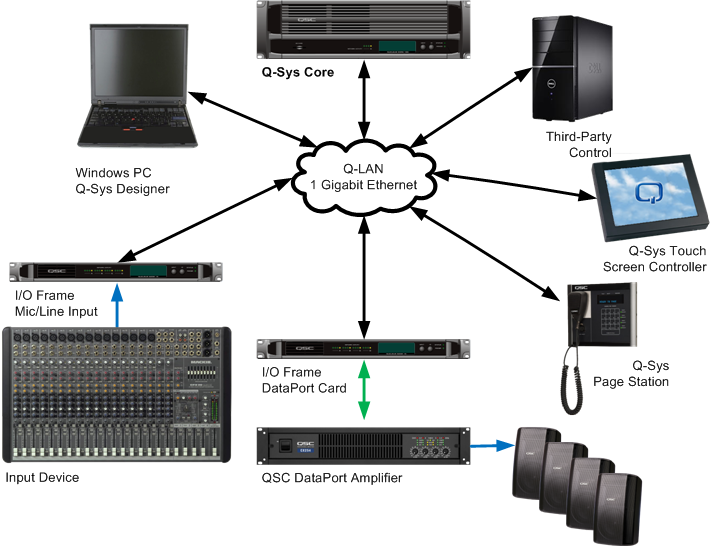
Ethernet Network
- 1 Gigabit Ethernet
- Latency - 0.667 ms across network
- 32-bit floating point format
- Redundancy - optional
- 1 to 16 channels per audio stream
- 1.65 to 3.31 Mb bandwidth per channel (dependent on the number of channels per stream)
System End-To-End Latency
Analog latency is measured using a MIC/LINE IN card and a LINE OUT or DataPort card.
- Input = 0.25 ms
- Network and Internal Processing = 2.0 ms
- Output = 0.25 ms
- Total = 2.5 ms
When using an AES3 card, the measurement is taken with and without Sample Rate Conversion (SRC)
With SRC
- Input = 4.958 ms
- Network and Internal Processing = 2.0 ms
- Output = 0.0625 ms
- Total = 5.02 ms
Without SRC
- Input = 0.0625 ms
- Network and Internal Processing = 2.0 ms
- Output = 0.0625 ms
- Total = 2.15 ms
Redundancy
VIDEO TUTORIAL: Video presentation available online for System Redundancy.
Q-SYS is capable of several redundant configurations to ensure a high level of overall system reliability.
- 2N Core redundancy - Two Cores, primary and redundant, communicating with each other and peripherals to verify system health, and to synchronize control settings.
- 2N I/O redundancy - For each I/O Frame, you can have a backup I/O Frame.
- N1 Amplifier redundancy - One amplifier can back up from one to eight amplifiers with the Q-SYS DataPort Amplifier Backup Panel.
- 2N Network redundancy - Two separate networks - In this configuration, you can have each Q-SYS Core and/or I/O Frame connected to both networks.
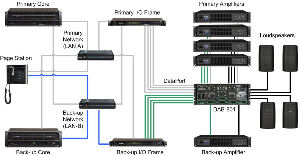
Network Redundancy
Both the Core and the I/O Frame have two network ports, LAN A (primary), and LAN B (backup). The LAN B port on I/O Frame becomes active when it is configured in Q-SYS Designer as "Is Network Redundant" and connected. Because the I/O Frame is configured in the design file, the Core recognizes it as being on LAN B as well as LAN A. During operation, the Core routes audio and control signals to both ports, so if LAN A, or a part of LAN A fails, the Core switches to LAN B with no failover time.
Q-SYS Hardware Redundancy
The Core and I/O Frame can have backups connected to the network. Both are identified in Q-SYS Designer as being redundant. The backup Core communicates with the primary to ensure it is up to date with any changes made on the primary, and to monitor the primary Core's health. The Core monitors the I/O Frames, if there is a problem detected with the primary I/O Frame, the Core switches to the backup. The audio inputs and outputs of the primary and backup I/O Frames are wired in parallel, meaning that the audio source drives two inputs. The audio outputs of an offline I/O Frame are disconnected by relays, so only the active I/O Frame, in a redundant pair, drives the outputs. See Q-SYS Redundancy for more information.
NOTE: If the entire system should lose power, any settings made to controls 30 seconds (or more) prior to losing power are automatically saved and restored when power is restored to the system.
The DataPort Amplifier Backup Panel (DAB-801) provides N+1 redundancy for the DataPort amplifiers and can be used in Life-Safety applications. The DAB-801 can support redundant network and I/O Frames, and four 2-channel or two 4-channel amplifiers per panel. Two panels can be stacked, doubling the amplifier count. See Amplifier Redundancy for more information.
© 2009 - 2016 QSC, LLC. All rights reserved. QSC and the QSC logo are trademarks of QSC, LLC in the U.S. Patent and Trademark office and other countries. All other trademarks are the property of their respective owners.
http://patents.qsc.com.