
Note: This topic is for reference only. Refer to the Q-SYS Core and I/O Frame User Manual or the Type 2 Q-SYS Core and I/O Frame User Manual for installation instructions.
The I/O Frame, running a customized Linux operating system, provides the main input and output connections for the Q-SYS system. The Core connects to the I/O Frame via the Q-SYS network, limiting the number of I/O Frames only to the size of your Core, and network bandwidth. An I/O Frame can contain up to four of the five available Audio I/O cards.
This topic covers the hardware aspect of the I/O Frame. For configuration details in Q-SYS Designer, refer to the I/O Frame configuration topic.
Note: When an I/O Frame is shipped, the I/O cards that are installed in the I/O Frame at shipping, are noted on the shipping label.
Type 2 hardware provides new cables and connectors between the I/O cards and main boards in Cores and I/O Frames. Due to this change, the Type 2 hardware is not physically compatible with the older hardware. You can still integrate the new I/O Frames and Cores in the same system with older hardware, but the I/O cards are not interchangeable. Type 2 hardware can be identified by a yellow label on the back of the Core and I/O Frame, and the bottom of the I/O cards.
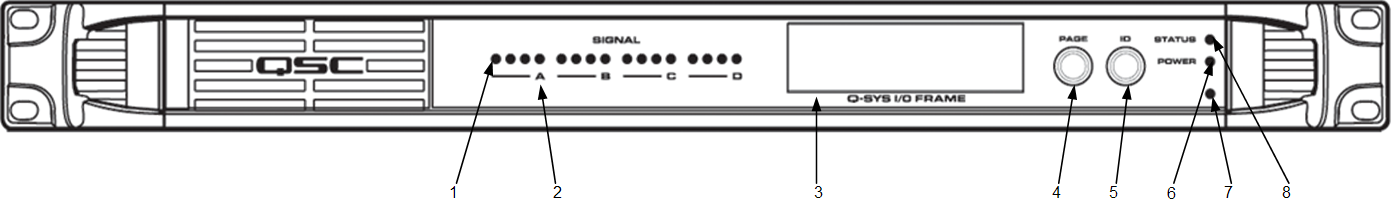
Five pages of information
Scrolls through the LCD readout pages
Insert a paperclip or similar device into the reset hole and hold for 10 seconds. A timer displays on the LCD. This resets all network settings to their factory defaults: IP Addresses, hostname, etc.
VIDEO TUTORIAL: For a comparison of the Front and Back Panel with a Core, watch the video presentation of the Core and I/O Frame.
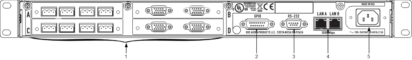
The I/O Frame allows for any combination of four, of the following I/O cards. Each card supports four channels.
Software and Firmware | Resources | QSC Self Help Portal | Q-SYS Help Feedback
Copyright © 2019 QSC, LLC. Click here for trademark and other legal notices. |
