
Note: This topic is for reference only. Refer to the I/O Frame 8s User Manual for installation instructions.
The I/O Frame 8s, running a customized Linux operating system, provides one of the main input and output connection devices for the Q-SYS system. The Core connects to the I/O Frame 8s via the Q-SYS network, limiting the number of I/O Frames only to the size of your Core, and network bandwidth. An I/O Frame 8s can contain up to eight of the available Audio I/O cards.
This topic covers the hardware aspect of the I/O Frame. For configuration details in Q-SYS Designer, refer to the I/O Frame configuration topic.
Note: When an I/O Frame is shipped, the I/O cards that are installed in the I/O Frame at shipping, are noted on the shipping label.
Type 2 hardware provides new cables and connectors between the I/O cards and main boards in Cores and I/O Frames. Due to this change, the Type 2 hardware is not physically compatible with the older hardware. You can still integrate the new I/O Frames and Cores in the same system with older hardware, but the I/O cards are not interchangeable. Type 2 hardware can be identified by a yellow label on the back of the Core and I/O Frame, and the bottom of the I/O cards.
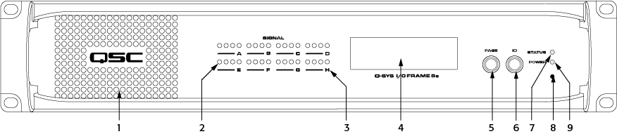
Five pages of information
Scrolls through the LCD readout pages
VIDEO TUTORIAL: For a comparison of the Front and Back Panel with a Core, watch the video presentation of the Core and I/O Frame.
Insert a paperclip or similar device into the reset hole and hold for 10 seconds. A timer displays on the LCD. This resets all network settings to their factory defaults: IP Addresses, hostname, etc.
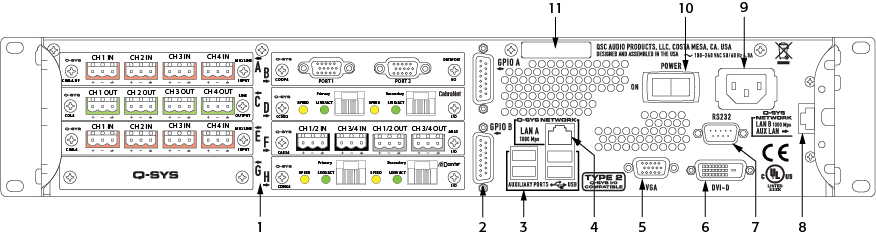
The I/O Frame allows for combinations of eight, of the following I/O cards.
Note: The types of cards shown in the example above are for illustration purposes only.
|
System Hardware |
I/O Frame |
|---|---|
|
Description |
System audio input and output device – eight I/O card slots. |
|
Front Panel Controls |
|
|
Front Panel Indicators |
|
|
Rear Panel Controls |
|
|
Rear Panel Connectors |
|
|
Capacity |
|
|
Local Audio Channels |
128 x 128 |
|
Network Audio Channels In |
128 |
|
Network Audio Channels Out |
128 |
|
Audio I/O Capacity |
Eight I/O Card Slots, Supporting: up to 32 analog I/O channels or up to 128 x 128 local digital I/O channels; Requires purchase of Q-SYS Type 2 audio I/O cards: CB, CIML4, CIML4-HP, COL4, CODP4, CAES4, CCN32, CDN64, CAN32. |
|
Line Voltage Requirements |
100 VAC - 240 VAC, 47 - 63 Hz |
| Current Draw |
Max 4.8 A @ 100 VAC |
|
Typical 1.9 A @ 100 VAC |
|
| Thermal | 650 BTU/h (typical) |
|
Dimensions (HWD) |
3.5" × 149" × 16.13" (88.9 mm × 482.6 mm × 425.7 mm) / 2RU |
|
Accessories Included |
|
Software and Firmware | Resources | QSC Self Help Portal | Q-SYS Help Feedback
Copyright © 2019 QSC, LLC. Click here for trademark and other legal notices. |
