DCIO/DCIO-H
The Digital Cinema Input/Output for Q-SYS (DCIO) is a cinema-specific interface that serves as the audio I/O for each screen in a Q-SYS enabled cinema complex.
Note: This topic provides an overview of the DCIO/DCIO-H peripheral. For installation and wiring instructions, see the Hardware User Guide online.
- Digital Cinema Inputs/Outputs for Q-SYS enabled cinemas and cinema complexes
- Routes inputs/outputs from projector IMB and alternate content sources to Q-SYS Core over Q-LAN, QSC's network distribution technology
- Mic/line input
- Line level monitor output
- Powered monitor output to passive speaker
- HDMI input/output for non-sync sources (DCIO-H version only)
- Dolby Audio™ (featuring Dolby Digital Plus™ and Dolby® Surround 7.1) and DTS-HD® decoding (DCIO-H version only)
- Four relay control outputs
- HI / VI outputs
- Automation inputs include RS-232 and GPI
Add the DCIO/DCIO-H to your design inventory from the Peripherals category. The following components are available for the DCIO/DCIO-H:
Front Panel

- OLED display – Displays information about the DCIO's settings and status.
- NEXT button – Cycles through the OLED information pages.
- ID button – Locates the DCIO in Q-SYS Designer GUI and Configurator.
- POWER LED – Illuminates blue when the DCIO is on.
- MUTE LED – Illuminates red when the DCIO master mute is engaged.
- MUTE button – Enables/Disable master mute.
- LEVEL rotary – Adjusts the master level.
Rear Panel
All inputs and outputs are configured in Q-SYS Designer software running on the Q-SYS Core to which the DCIO is connected.
Note: For wiring information and pinouts, see the Hardware User Guide online.

- MIC / LINE INPUT – Standard three-conductor XLR connector, balanced input, phantom power available in Q-SYS Designer. Used for: mono, non-sync sources including microphone for in-auditorium announcements, and SPL metering.
- Hearing Impaired and Visually Impaired Outputs (H.I. and V.I.) – Five-terminal Euro-style receptacle, balanced outputs, used for: hearing- and / or visually-impaired special mixes. The receptacle label provides a pin-out of the signals. The ground is common to both.
Tip: A standard three-terminal Euro-style connector may be used if only one output is required. Make sure the plug is all the way to the right, or all the way to the left of the five-terminal receptacle.
- RELAY OUTPUTS – Two six-terminal Euro-style receptacles, mechanically de-coupled control outputs, floating relay contacts, rated for 30 VDC at 1A. Each relay output has one common contact (C), one normally open contact (NO) and one normally closed (NC) contact. When not energized, C is connected to NC and NO is not connected. When energized, C is connected to NO and NC is not connected. Used for controlling curtains, lighting, etc.)
- AES3 INPUTS – RJ45, CAT-5 or better to connect to sources using the same type connector and pinout.
AES3 1–8 – AES3 pairs 1 through 4 (digital audio channels 1–8)
AES3 9-16 – AES3 pairs 5 through 8 (digital audio channels 9–16)
Used for primary content audio from the server or media block.Note: The AES3 connectors are NOT network connections.
- LAN connections – RJ45, CAT-5E or better.
LAN A – Used for primary Q-LAN connection, required.
LAN B – Used for redundancy. - POWER ON / OFF switch
- IEC connector – AC mains power connector
- Line Inputs (LR) – Standard 3.5mm TRS jack, unbalanced, stereo, analog, line-input. Used for non-sync sources appropriate for alternative content, advertising, corporate or live event feeds.
- Monitor Outputs – Five-pin, Euro-style connector; three-pins for Line and two pins for Speaker. The supplied connectors have an extended tab with holes for securing the wiring to the connector. Refer to the pin-out label on the rear panel for wiring.
- Line – The Line output provides a balanced output at 14 dBu, via three pins of the Euro-style connector.
- Speaker – Powered output, 10 watts maximum, via two pins of the Euro-style connector.
Tip: A standard two- or three-terminal plug may be used if only one output is required.
- AUTOMATION INPUTS – RJ45, contact closures. The Automation Inputs can be connected to relay contacts or a switch (control presets, mute etc).
- RS-232 Serial Communications – Three-pin Euro-style connector for (Rx), transmit (Tx) and ground pin. Used for third-party control or automation.
- HDMI In – DCIO-H model only. Extracts audio from incoming HDMI stream and passes the stream directly to output HDMI port for connection to a downstream video device. Up to 8 channels of PCM audio are supported. Additionally, Dolby Digital Plus™ and DTS-HD® decoders will be automatically applied if those bitstreams are detected.
- HDMI Out – DCIO-H model only. See HDMI In.
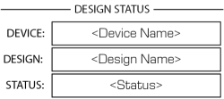
Design Status

- Device – The name of the Core as defined in Q-SYS Designer.
- Design – The name of the currently running design.
- Status –
- OK – Audio is good, hardware is good.
- Compromised – Audio is good but a redundancy mechanism is active (one LAN down but the other is still up) or a non-fatal hardware problem exists.
- Fault – Audio is not passing, or hardware is malfunctioning or mis-configured
- Missing – A piece of hardware, defined in the design, has not been discovered. Audio is not passing through that piece of hardware.
- Initializing – Starting the firmware, configuration update, and the design. Audio is obviously not available during initialization.
- Not Present – A virtual component in the design, that is designated as Dynamically Paired, and Not Required, has no hardware assigned to it.
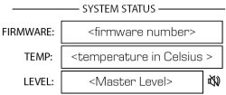
System Status

- Firmware – The version number of the firmware currently installed on the DCIO.
- Temp – The current chassis temperature of the DCIO.
- Level – The current master level setting -100 dB to +20 dB. Adjust with front-panel rotary or in Q-SYS Designer.
- Mute – The current master mute status. Controlled by front panel Mute button or in Q-SYS Designer.
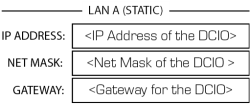
LAN A

You can edit this information in the Q-SYS Configurator.
- Static, Auto or No Link – Displays next to LAN A, indicates if the device's IP Address is Static, Automatic, or No Link.
- IP Address – The IP Address assigned to the Core's LAN A. LAN A is the primary Q-LAN connection to the Core, and is required.
- Net Mask – The Net Mask assigned to the Core.
- Gateway – The Gateway assigned to the Core.
LAN B
LAN B is used for redundancy, and is not required. The information is the same as LAN A.
AES 1–8 and AES 9–16 Channel Status

You must have AES 9–16 Enabled in Q-SYS Designer to see channels 9–16.
- Mute – Displays a "muted loudspeaker" when the channel is muted.
- Signal – Displays a blinking or solid circle when there is a signal present on the associated channel, an empty circle if there is no signal.
HDMI 1–8 Channel Status

- Mute – Displays a "muted loudspeaker" when the channel is muted.
- Signal – Displays a blinking or solid circle when there is a signal present on the associated channel, an empty circle if there is no signal, and nothing if that channel doesn't exist in the current stream.
- Bitstream Type – Displays the type of bitstream detected at HDMI input.
- Sample Rate – Displays the sample rate detected at the HDMI Input.
Analog In Channel Status

- Mute – Displays a "muted loudspeaker" when the channel is muted.
- Signal – Displays a blinking or solid circle when there is a signal present on the associated channel, an empty circle if there is no signal.
- Clip – Displays a solid circle when the input signal is clipping.
- +15V – Displays a solid circle when phantom power is turned on for the Mic Input.
Analog Out Channel Status

- Mute – Displays a "muted loudspeaker" when the channel is muted.
- Signal – Displays a blinking or solid circle when there is a signal present on the associated channel, an empty circle if there is no signal
- Clip – Displays a solid circle when the input signal is clipping.
|
Dimensions (HxWxD) |
1.75 (2 RU) x 19 x 11.2 inches (44 x 483 x 282.5 mm) |
|
Line voltage requirements |
100 VAC – 240 VAC, 50/60 Hz |
|
Accessories included |
1m UL/CSA line cord, Euro-style connectors for outputs and relay connections |
|
Front Panel Controls and Indicators |
|
|
Level adjust |
Rotary encoder |
|
Power On indicator |
Blue LED |
|
Display |
Monochrome 304x96 blue OLED graphics display |
|
Other |
Momentary mute button Mute LED (red) Screen Navigation (Next) and ID buttons |
|
Rear Panel Connectors |
|
|
Mic/Line input |
XLR — Mic (+ phantom power) or line level |
|
Line Input |
3.5 mm TRS |
|
H.I./V.I. output |
5-pin Euro-style (x1) – common GND |
|
Line/Speaker Outputs |
Line: 3-pin Euro-style, Speaker: 2-pin Euro-style |
|
Relay outputs |
3-pin Euro-style (x4) |
|
AES3/EBU Inputs |
Ch. 1–16 (RJ45 x2) |
|
Automation Inputs |
RJ45, RS-232 |
|
Dual Gigabit Ethernet Q-LAN ports |
LAN A, LAN B (RJ45 x2) |
|
HDMI input/output (DCIO-H only) |
HDMI 2.0, Type A female connectors |
|
Power switch |
Rocker switch |
|
IEC Power Connector |
|
|
Audio Performance |
|
|
A/D conversion |
32-bit delta-sigma, 48 kHz |
|
Frequency response |
20 Hz to 20 kHz (+- .5dB) |
|
AES/EBU Digital Inputs (RJ45) |
|
|
Input stage type |
Balanced input |
|
Input impedance |
110 ohms |
|
Input sample rate |
44.1 kHz, 48 kHz or 96 kHz |
|
HDMI Digital Inputs (DCIO-H only) |
|
|
Bitstream support |
8ch PCM, Dolby Digital Plus™ and DTS-HD® |
|
Input sample rate |
44.1 kHz, 48 kHz (Dolby Digital Plus™) |
|
|
All (PCM and DTS-HD®) |
|
Mic/Line Input (XLR) |
|
|
Input stage type |
Active balanced input |
|
Input impedance |
2.2k Ohms |
|
Max analog input level |
26 dBu |
|
Dynamic range (unweighted) |
> 111 dB |
|
Dynamic range (A-weighted) |
> 114 dB |
|
THD+N at 10 dB below clip (26dBu sens) |
< 0.02% |
|
THD+N at 10 dB below clip (21dBu sens) |
< 0.003% |
|
Input gain |
0 to 60dB in 1 dB steps |
|
CMRR typical 2 |
20 Hz to 20 kHz: > 50dB |
|
EIN |
< -122 dB |
|
Phantom power voltage |
15V |
|
Stereo Line Inputs |
|
|
Connector |
3.5mm TRS mini jack |
|
Input stage type |
Unbalanced input |
|
Input impedance (4dBu sens) |
> 10k Ohms |
|
Max analog input level (4dBu sens) |
15 dBu (4.4 Vrms) |
|
Input impedance (-10dBV sens) |
2.7k Ohms |
|
Max analog input level (-10dBV sens) |
1 dBV (1.2 Vrms) |
|
Headroom (all sens) |
> 10dB |
|
Dynamic range (unweighted) |
> 109 dB |
|
Dynamic range (A-weighted) |
> 112 dB |
|
THD+N at 2 dB below clip |
< 0.003% |
|
HI/VI Outputs |
|
|
Connector |
5-pin Euro-style with common GND |
|
Output stage type |
Balanced output |
|
Max output level |
18 dBu (adjustable) |
|
Dynamic range (unweighted) |
> 110 dB |
|
THD+N at 2dB below clip |
< .009 % |
|
Monitor Output |
|
|
Connector |
Euro-style |
|
Output stage type |
Unbalanced output |
|
Max output level |
14 dBu |
|
Dynamic range (unweighted) |
> 109 dB |
|
THD+N at 2dB below clip |
< .005 % |
|
Powered Monitor Output |
|
|
Unbalanced output |
Euro-style (2 pins) |
|
Max. Output Power |
10 W |
|
Other |
|
|
Relay outputs (4) |
3-pin Euro-style Normally open (NO), normally closed (NC), and common Max 30 VDC @ 1A |
|
Automation inputs (RJ45 - 6 GPI) |
Max input voltage 5V (3.3V typical) TTL compatible dry contact closure |
|
Line voltage |
100 VAC to 240 VAC, 50/60 Hz |
For more information, and to see a list of related documentation, visit the DCIO/DCIO-H product page on the QSC website.
