QIO-IR1x4
The Q-SYS QIO-IR1x4 is a network control endpoint native to the Q-SYS Ecosystem, serving as an IP-to-IR bridge that enables network-based infrared control distribution. The compact form factor includes surface mounting hardware permitting discreet and strategic mounting while an optional rack kit fits one to four devices into a standard 1U nineteen-inch format. Up to four devices may be daisy-chained off one access switch port, provided +24 VDC power is available. Alternatively, each may be individually powered over Ethernet.
Note: This topic provides an overview of the QIO-IR1x4. For specifications and installation documentation, see the QIO-IR1x4 product page on the QSC website.
-
Native control I/O expander for Q-SYS
-
First native IR connectivity solution for Q-SYS
-
One (1) IR receiver input and four (4) IR emitter outputs
-
Power-over-Ethernet capable
-
Daisy-chain up to four QIO network I/O expanders on a single network run (with local daisy-chained DC power)
-
Simple drag-and-drop integration and comprehensive management via Q-SYS Designer Software and Q-SYS Reflect
-
Surface- or rack-mountable
-
Includes surface mounting hardware
-
QIO-RMK rack mounting kit sold separately
-
QIO-PSU DC power supply sold separately
Inventory Components
These components are available from the Inventory tree once you have added a QIO-IR1x4:
Control Components
These related components are available from the Schematic Elements > Control Components category:
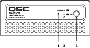
Front Panel

-
Power LED – Illuminates blue when the Q-SYS QIO-IR1x4 is powered on.
-
ID LED – LED blinks green when placed into ID Mode via ID Button or Q-SYS Configurator.
-
ID Button –Locates the QIO-IR1x4 in Q-SYS Designer Software and Q-SYS Configurator.
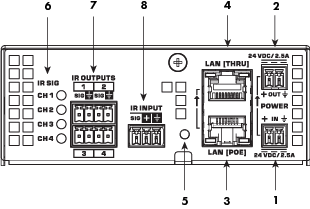
Rear Panel

-
External Power Input 24V DC 2.5 A – Auxiliary power, 24 VDC, 2.5 A, 2-pin Euro connector.
-
Daisy-Chain Power Output 24V DC 2.5 A – Auxiliary power, 24 VDC, 2.5 A 2-pin Euro connector.
-
LAN [PoE] – RJ-45 connector, 802.3af PoE Type 1 Class 1 power, Q-LAN.
-
LAN [THRU] – RJ-45 connector, Ethernet daisy-chaining.
-
Device Reset – Use a paperclip or similar tool to restore default network settings and recover factory default settings. Before attempting a reset, refer to the Device Reset section.
-
IR SIG LEDS – Indicate transmit activity for CH/IR Output 1-4.
-
IR Outputs – Configurable in Q-SYS Designer Software as IR or Serial RS232. See the IR Port Pinouts section.
-
IR Input – Provides 3.3VDC and receives IR data. See the IR Port Pinouts section.
The QIO-IR1x4 features four IR outputs and one IR input:
-
Outputs 1-4 are configurable in Q-SYS Designer Software for IR or Serial RS232 mode.
-
Input provides 3.3VDC and receives IR data.
IR Output 1-4: IR Mode Pinout
| Pin | Signal Flow | Description |
|---|---|---|
| SIG | Output | IR transmit data |

|
N/A | Signal reference |
IR Output 1-4: Serial RS232 Mode Pinout
| Pin | Signal Flow | Description |
|---|---|---|
| SIG | Output | RS232 transmit data |

|
N/A | Signal reference |
IR Input Pinout
| Pin | Signal Flow | Description |
|---|---|---|
| SIG | Input | IR receive data |

|
Output | 3.3VDC |

|
N/A | Signal reference |
Product specifications and dimension drawings for the QIO-IR1x4 can be found on the QIO-IR1x4 product page.
You can perform either a short reset or long reset:
- Use a Short Reset to restore connectivity to a device in the event that unintended network settings were specified in Q-SYS Peripheral Manager or the device is otherwise unreachable. A short reset will restore device IP settings back to Auto mode (DHCP) and delete all Static Routes. The configured hostname is retained.
- Use a Long Reset to restore the device to factory condition. This is useful for deeper troubleshooting, or when preparing the device for decommissioning or transfer.
CAUTION: A Long Reset clears all network settings (including hostname), disables 802.1x, deletes user-installed device certificates, deletes all logs, and clears the device password.
Performing a Short Reset
- Press and hold the Reset Button until the Status LED (NL, NM Series) or Power LED (QIO Series) begins flashing blue slowly – approximately 10 seconds.
- Release the button before 20 seconds elapse.
- The device performs its prescribed Short Reset and reboots.
Note: To cancel the Short Reset, release the button before 10 seconds has elapsed.
Performing a Long Reset
- Press and hold the Reset Button until the Status LED (NL, NM Series) or Power LED (QIO Series) begins flashing blue rapidly – approximately 20 seconds.
- Release the button when the LED begins flashing rapidly.
- Within 30 seconds, press the Reset Button again to confirm the reset.
- The device performs its prescribed Long Reset and reboots.
Note: To cancel the Long Reset, do not press the Reset Button again during the 30 second confirmation period.
