Note: This topic is for reference only. Refer to the CXD-Q Amplifier User Manual for installation instructions and detail.
The CXD-Q Amplifier comes in three models CXD4.2Q, CXD4.3Q and CXD4.5Q each with different power output. The amplifier is placed in a Q-SYS design and configured for the output configuration. The inputs and outputs of the amplifier are separated in the amplifier giving you the capability of using the inputs in the same way you would use a Line Input card. In addition, you can send different audio to the amplifier's outputs than what is provided on the amplifier inputs. Of course you can connect the amplifier inputs and outputs in the design.
This topic covers the hardware aspect of the CXD-Q amplifiers. For configuration details in Q-SYS Designer, refer to the CXD-Q Status, CXD-Q Amplifier In Component, CXD-Q Amplifier Out Component, and the CXD-Q Amplifier GPIO Component topics.
CXD4.2Q |
CXD4.3Q |
CXD4.5Q |
|||||||
|
4 Channels 1 100 Vrms 2 70 Vrms 2 8Ω 4Ω 2Ω |
|
|
|
||||||
|
2 Channels 1 8Ω 4Ω 2Ω |
|
|
|
||||||
|
1 Channel 1 8Ω 4Ω 2Ω 1Ω |
|
|
|
||||||
|
Typical Distortion 8Ω 4Ω |
0.01–0.03% 0.03–0.06% |
0.01–0.03% 0.03–0.06% |
0.01–0.03% 0.03–0.06% |
||||||
|
Maximum Distortion 4Ω–8Ω |
1.00% |
1.00% |
1.00% |
||||||
|
Frequency Response (8Ω) |
0 Hz–15 kHz ±0.2 dB 20 Hz–20 kHz +0.2 dB / -0.7 dB |
20 Hz–15 kHz ±0.2 dB 20 Hz–20 kHz +0.2 dB / -0.7 dB |
20 Hz–15 kHz ±0.2 dB 20 Hz–20 kHz +0.2 dB / -0.7 dB |
||||||
|
Noise Unweighted Output Unmuted Weighted Output Muted |
-101 dB -109 dB |
-101 dB -109 dB |
-101 dB -109 dB |
||||||
|
Gain (1.2V setting) |
34.0 dB |
38.4 dB |
38.4 dB |
||||||
|
Damping Factor |
>150 |
>150 |
>150 |
||||||
|
Q-SYS Analog Signal Inputs |
Four mic/line, configured and routed in Q-SYS Designer; not connected to amplifier output channels |
||||||||
|
Input Impedance |
>10k ohms, balanced or unbalanced |
||||||||
|
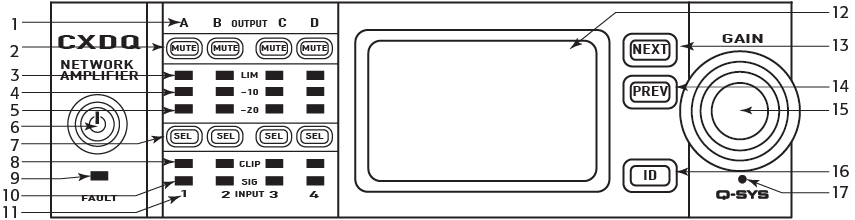
Front Panel Controls and Indicators |
Power • Channel MUTE Buttons • Channel SELECT Buttons • Channel Input Signal and CLIP LED Indicators • Channel Output and LIMIT LED Meters • NEXT, PREV, ID Buttons • Control Knob • FAULT LED • Pinhole Reset |
||||||||
|
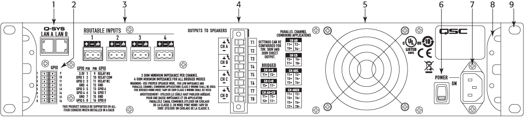
Rear Panel Controls and Indicators |
AC power disconnect switch LAN A link and activity LEDs LAN B link and activity LEDs |
||||||||
|
Rear Panel Connectors Input Output (Loudspeakers) Network GPIO |
3-pin Euro style (4) 8-pin Euro style LAN A / LAN B RJ45 16 pin Euro style |
||||||||
|
Amplifier and Load Protection |
Short Circuit, Open Circuit, Thermal, RF Protection. On / Off Muting, DC Fault Shutdown, Active Inrush Limiting, Input Current Limiting |
||||||||
|
AC Power Input |
Universal Power Supply 100-132/200–240 VAC, 50–60 Hz |
Universal Power Supply 100–240 VAC, 50–60 Hz |
|||||||
|
Dimensions (HWD) |
3.5" × 19" × 12" (89 mm × 482 mm × 305 mm) |
3.5" × 19" × 16" (89 mm × 482 mm × 406 mm) |
3.5" × 19" × 16" (89 mm × 482 mm × 406 mm) |
||||||
|
Weight Net / Shipping |
18.5 lb (8.4 kg) / 22 lb (10.0 kg) |
21.0 lb (9.5 kg) / 25 lb (11.3 kg) |
22.0 lb (10.0 kg) / 26 lb (11.8 kg) |
||||||
|
Agency Approvals |
UL, CE, RoHS/WEEE compliant, FCC Class A (conducted and radiated emissions) | ||||||||
Software and Firmware | Resources | QSC Self Help Portal | Q-SYS Help Feedback
Copyright © 2019 QSC, LLC. Click here for trademark and other legal notices. |
