Core 510i
The Q-SYS Core 510i represents the second generation of QSC’s Integrated Core Platform. It features eight I/O card slots, which can be populated with any combination of Q-SYS I/O cards allowing for up to 128x128 local channels plus a total of 256x256 network channels for diverse connectivity options.
|
Local I/O Channels |
Up to 32 analog, up to 128x128 AES/CobraNet/Dante/AVB |
|
Network Audio Channels |
256 x 256 |
|
AEC Processors |
64 |
|
Multitrack Audio Players |
16 (upgradable to 128) |
|
Local I/O Card Capacity |
8 |
|
VoIP Instances |
64 |
Note: This topic provides an overview of the Core 510i. For installation and connection instructions, see the Hardware User Guide online.
- Q-SYS Core processing in a flexible chassis featuring 8 onboard I/O card slots
- Install any combination of Q-SYS I/O Cards for maximum flexibility
- Audio, video and control processing on a dedicated Linux™ realtime OS
- Software configurable as either a Core 510i processor, or an I/O-510i expander
- Built using standard computer industry hardware and IT industry networking protocols
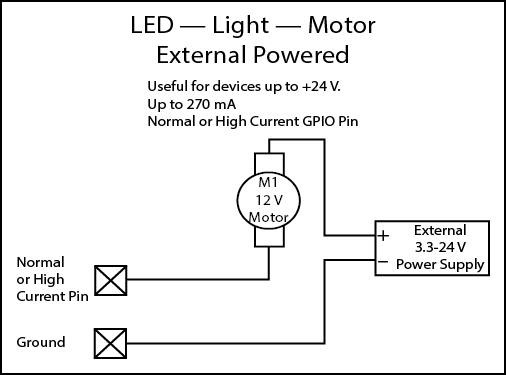
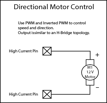
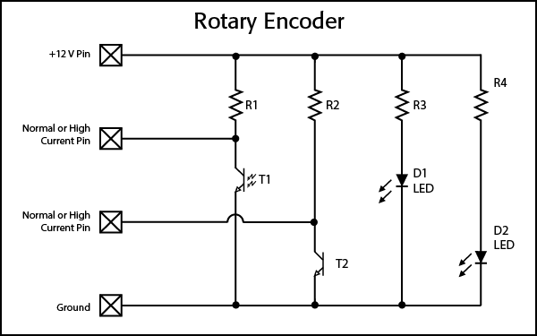
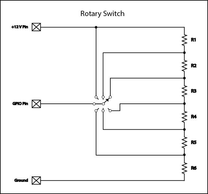
- Control and integrate external devices using TCP/IP, RS232 and GPIO
- Design with powerful and intuitive Q-SYS Designer Software application
- Seamlessly integrates with Q-SYS AV-to-USB bridging peripherals
- Provides simple integration with QSC amplifiers and loudspeakers
- Multiple levels of system redundancy
The following Q-SYS Designer components are available for the Core 510i, depending on its Properties:
Standard Components
- Status (Core)
- GPIO (Core 250i, 500i, 510i, 1100, 3100, and I/O Frame)
- Loudspeaker Monitor
- Serial Port (Core, I/O Frame, I/O-22)
I/O Card Components
For a description of individual I/O card hardware, see I/O Cards.
Front Panel

- OLED Display – Displays information about the Core's settings and status.
- NEXT button – Cycles through the OLED information pages
- ID button – Locates the Core in Q-SYS Designer GUI and Configurator
- POWER LED – Illuminates blue when the Core is on
- USB Ports – USB Type A Host connectors (2)
Rear Panel

- Eight Audio I/O Card Bays – Accept Q-SYS Type 2 Audio I/O Cards (supports up to 128x128 local audio channels)
- GPIO A and GPIO B – Female DA-15 connectors for Q-SYS control I/O
- RS232 – Male DE-9 serial communications interface
- HDMI – Video Output
- AC Mains – IEC 60320 C14 receptacle
- AUX LAN – RJ45: Data, VoIP, WAN streaming, management Auxiliary Ports – USB Type A Host Ports
- LAN A – RJ45: Q-LAN, AES67, Audio, VoIP, management Auxiliary Ports – USB Type A Host Ports
- LAN B – RJ45: Q-LAN, AES67, Audio, VoIP, management
Design Status
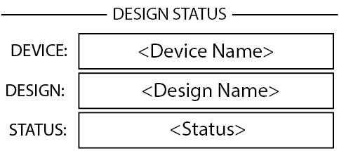
- Device – The name of the Core as defined in Q-SYS Designer.
- Design – The name of the currently running design.
- Status – Indicates health of Core in design:
- OK – Audio, Video and Control (AVC) engine is good.
- Compromised – AVC engine is good, but a redundancy mechanism is active (one LAN down but the other is still up) or a non-fatal hardware problem exists (fans too slow, temperature higher than expected, etc.)
- Fault – AVC engine is stopped, or hardware is malfunctioning or mis-configured
- Missing – A piece of hardware, defined in the design, has not been discovered. AVC engine is not communicating with that piece of hardware.
- Initializing – Starting the firmware, configuration update, or design update.
- Not Present – A virtual component in the design, that is designated as Dynamically Paired, and Not Required, has no hardware assigned to it.
System Status
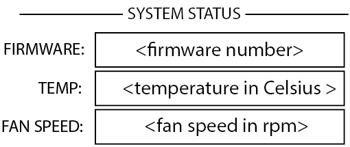
- Firmware – A three-section number identifying the major release, minor release, and maintenance release. For example, 6.0.0.
- Temp – The current chassis temperature of the Core.
- Fan Speed – This number varies with the temperature.
LAN A
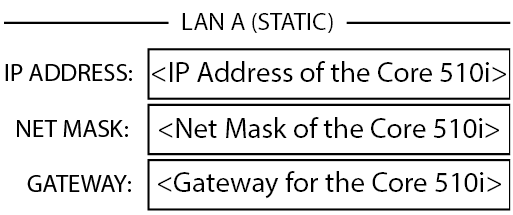
- Static or Auto – Displays next to LAN A, indicates if the Core's IP Address is Static or Automatic.
- IP Address – The IP Address assigned to the Core's LAN A. LAN A is the primary Q-LAN connection to the Core, and is required.
- Net Mask – The Net Mask assigned to the Core.
- Gateway – The Gateway assigned to the Core.
Note: You can edit this information in Q-SYS Core Manager.
LAN B
LAN B is used for redundancy or segregation of various data types on to different networks but is not required for device operation. The information is displayed in the same format as LAN A.
LAN AUX
LAN AUX is used for remote monitoring, WAN and VOIP connectivity, and is not required. The information is displayed in the same format as LAN A.
Slots A - H
There is a total of 8 slots that can accommodate any combination of Q-SYS I/O Cards that are Type 2 format. The status for these cards are shown on the front panel by pressing the NEXT button.
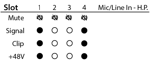
The Mic/Line In H.P. card status screen shows the Mute state, Signal presence, Clip indication and +48V state of each of the 4 input channels.
- Mute – Displays a "muted loudspeaker" when the channel is muted.
- Signal – Displays a solid circle when there is a signal present on the associated channel.
- Clip – Displays a solid circle under the channel having an output signal over driving the associated channel output.
- +48V - Displays a sold circle when phantom power is active on the associated channel.
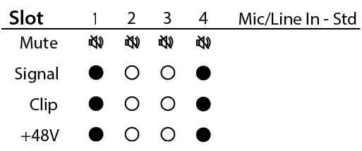
The Mic/Line In Standard card status screen shows the Mute state, Signal presence, Clip indication and +48V state of each of the 4 input channels.
- Mute – Displays a "muted loudspeaker" when the channel is muted.
- Signal – Displays a solid circle when there is a signal present on the associated channel.
- Clip – Displays a solid circle under the channel having an output signal over driving the associated channel output.
- +48V - Displays a solid circle when phantom power is active on the associated channel.
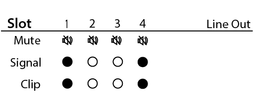
The Line Out card status screen shows the Mute state, Signal presence, and Clip status of each of the 4 output channels.
- Mute – Displays a "muted loudspeaker" when the channel is muted.
- Signal – Displays a solid circle when there is a signal present on the associated channel.
- Clip – Displays a solid circle under the channel having an output signal over driving the associated channel output.
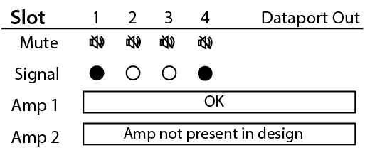
The Dataport Out card status screen shows the Mute state, Signal presence, and connected amplifier status for both ports.
- Mute – Displays a "muted loudspeaker" when the channel is muted.
- Signal – Displays a solid circle when there is a signal present on the associated channel.
- Amp 1 – Displays the status of the connected amplifier.
- Amp 2 - Displays the status of the connected amplifier.
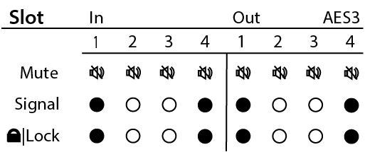
The AES3 card status screen shows the Mute state, Signal presence, and Lock state for 4 input and 4 output channels.
- Mute – Displays a "muted loudspeaker" when the channel is muted.
- Signal – Displays a solid circle when there is a signal present on the associated channel.
- Lock – Displays a solid circle when the AES3 clock is in sync and locked.
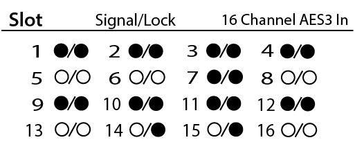
The AES3 16 channel card status screen shows the Signal presence, and Lock state for all 16 input channels.
- Signal – Displays a solid circle when there is a signal present on the associated channel.
- Lock – Displays a solid circle when the AES3 clock is in sync and locked for the associated channel.
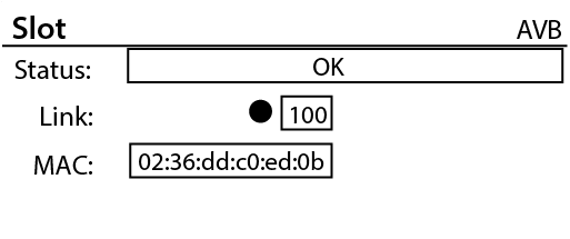
The AVB card status screen shows the Status of the card, Link state and speed of the network connection, and the MAC address of the card itself.
- Status – Displays the status of the AVB card.
- Link – Displays a solid circle when there is a valid connection with an AVB network or device and indicates the network connection speed in Mbps.
- MAC – Displays the MAC (Media Access Control) address of the AVB card.
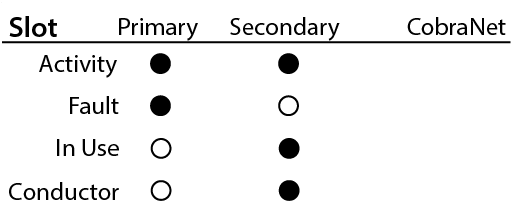
The CobraNet card status screen shows the Activity state, Fault state, In Use state and Conductor state of the Primary and Secondary network ports.
- Activity – Displays a solid circle when the Primary or Secondary port is active.
- Fault – Displays a solid circle under the channel having a communication fault while sending or receiving a bundle.
- In Use – Displays a solid circle when there is an active connection to a CobraNet network or device on the associated LAN port (primary or secondary.) The image shows that the secondary port is active.
- Conductor - Displays a solid circle when the Primary or Secondary port is the Conductor.
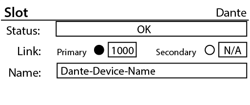
The Dante card status screen shows the Status of the card, Link state and connection speed of the Primary and Secondary network ports, and the Name of the device as seen by other Dante devices on the network.
- Status – Displays the status of the Dante card.
- Link – Displays a solid circle when there is a valid connection with a Dante network or device. The image shows that the Primary port has established a link at 1000 Mbps.
- Name – Displays the name of the Dante device that will be seen by other connected Dante devices.
GPIO Pin Assignments
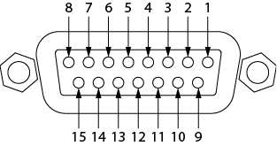
|
DB15 Pin |
Signal Name |
Signal Type |
Description |
|---|---|---|---|
|
1 |
RNO |
Relay Contact |
Relay - normally open |
|
2 |
RNC |
Relay Contact |
Relay - normally closed |
|
3 |
GPIO 1 |
Normal Current |
GPIO pin |
|
4 |
GPIO 3 |
Normal Current |
GPIO pin |
|
5 |
POWER |
Power |
+ 12V DC |
|
6 |
GPIO 5 |
High Current |
GPIO pin -high current capable |
|
7 |
GPIO 7 |
High Current |
GPIO pin -high current capable |
|
8 |
GND |
Ground |
Ground |
|
9 |
RC |
Relay Contact |
Relay - common |
|
10 |
GND |
Ground |
Ground |
|
11 |
GPIO 2 |
Normal Current |
GPIO pin |
|
12 |
GPIO 4 |
Normal Current |
GPIO pin |
|
13 |
POWER |
Power |
+ 12V DC |
|
14 |
GPIO 6 |
High Current |
GPIO pin -high current capable |
|
15 |
GPIO 8 |
High Current |
GPIO pin -high current capable |
GPIO Specifications
Relay Pins |
Normal Current Pins |
Description |
|
Maximum Voltage, relative to Ground: 30V |
Maximum Input Range: 0 V to 32 V |
Maximum Input Range: 0 V to 32 V |
|
Maximum Current through Rlay: 1 Amp |
Analog Input Range: 0 V to 24 V |
Analog Input Range: 0 V to 24 V |
|
Digital Input, Low: 0.8 V maximum |
||
Power Pins |
Digital Input, High: 2.0 V minimum |
|
|
Output Voltage: 11 V min, 13 V max |
Digital Output, Low: 0.4 V maximum |
|
|
Maximum Output Current: 400 mA |
Digital Output, High: 2.4 V min, 3.3 V max |
|
|
Digital Output Impedance: 1K Ohm |
||
|
High Current Output, Low: 0.4 V maximum |
||
|
High Current Output, High: Not supported |
High Current Output, High: 11 V min, 13 V max |
|
|
High Current Output, sink: 280 mA High Current Output, source: Not supported |
High Current Output, sink or source: 280 mA |
Note: The maximum current sourced by one GPIO connector (including both High Current and Power Pins) is 400mA.
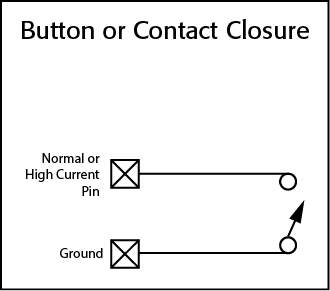
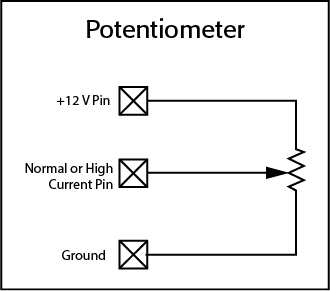
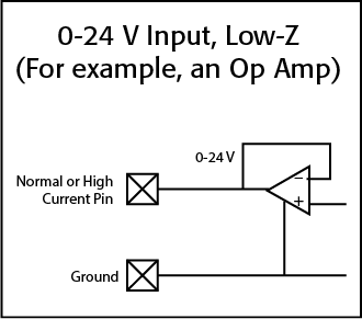
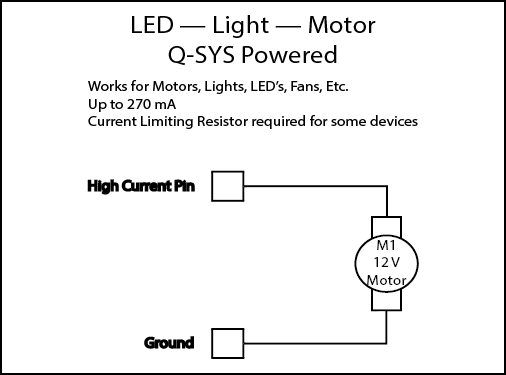
GPIO Examples
|
Description |
Audio, Video and Control processing engine with integrated I/O (or I/O Frame peripheral for I/O expansion) |
|
Operation Mode |
"Core" mode - Audio, Video and Control processing engine for Q-SYS system with 8, Type 2 I/O card slots for high channel count operation "I/O Frame" mode - I/O expansion with 8, Type 2 I/O card slots for high channel count operation |
|
Software Requirements |
6.0.0 or higher |
|
Capacities |
|
|
Network Channel Capacity |
256 x 256 ("Core" mode), 128 x 128 ("I/O Frame" mode) |
|
I/O Capacity |
8 audio I/O card slots - accomodates up to 128 x 128 total onboard I/O channels |
|
AEC Capacity |
510i: 64 processors at 200ms tail length (available in "Core" mode only) 510c: 16 processors at 200ms tail length (available in "Core" mode only) |
|
Multitrack Player Capacity |
16 tracks, expandable to 128 tracks (accessible in "Core" mode only, note: 32, 64 or 128 track upgrade options are available) |
|
Media Drive Capacity |
Approximately 6GB on the internal drive (accessible in "Core" mode only, note: upgrade options are available) |
|
I/O Card Options |
COL4: Line Output card (4 channels) CODP4: DataPort card (4 channels) CIML4: Standard Mic/Line Input card (4 channels) CIML-HP: High Performance Mic/Line Input card (4 channels) CAES4: AES3 Digital I/O card (4 x 4 channels) CIAES16: AES3 Digital Input card (16 channels) CCN32: CobraNet Network Bridge card (up to 32 x 32 channels) CAN32: AVB Network Bridge card (up to 32 channels) CDN64: Dante Network Bridge card (up to 64 x 64 channels) |
|
Media Drive Options |
M2-MD-S: 128GB M2-MD-M: 256GB M2-MD-L: 512GB |
|
Multitrack Player Options |
MTP-32: 32 tracks of simultaneous media file playback MTP-64: 64 tracks of simultaneous media file playback MTP-128: 128 tracks of simultaneous media file playback * MTP Options require the purchase of a Media Drive (128 GB or larger) |
|
Controls and Indicators |
|
|
Front Panel Controls |
"NEXT" OLED page forward capacitive touch button "ID" capacitive touch button "Clear Network Settings" invoked when "NEXT" and "ID" buttons are pressed simultaneously |
|
Front Panel Connectors |
AUX USB: USB Host x 2 (Type A connections) |
|
Front Panel Indicators |
Blue "POWER" LED 304 x 96 monochrome OLED display |
|
Rear Panel Connections |
RS232: Male 9-pin D shell connector (9-pin) Video Out: HDMI AUX USB: USB Host x 4 (Type A connections) AUX Network: RJ45 10/100/1000 Mbps Management Network GPIO: Female 15-pin D shell connector x 2 (DA-15) Media Network LAN A: RJ45 1000 Mbps (QLAN, AES67, VoIP, WAN, Media Streaming, etc) Media Network LAN B: RJ45 1000 Mbps (QLAN, AES67, VoIP, WAN, Media Streaming, etc) AC Mains Power: IEC connector |
|
Rear Panel Indicators |
"Link", "Speed" and "Activity" LEDs on all LAN prots |
|
Miscellaneous |
|
|
Line Voltage |
100 VAC - 240 VAC, 50-60 Hz |
|
Current Draw |
3.7A Max @ 100 VAC (actual current draw depends on configuration options such as; I/O cards and/or Media Drive, DSP and Network loading) |
|
Operating Temperature Range |
0°C - 50°C |
|
BTU/Hour |
600 (power conversion estimate under typical load) |
|
Humidity |
5-85% RH non-condensing |
|
Expected Product Life Cycle |
20 years |
|
Product Storage Temperature |
-20°C to +70°C |
|
Regulatory |
FCC 47 CFR Part 15 Class A, IC ICES-003, CE (EN55032, EN55035), EU RoHS directive 2011/65/EU, WEEE directive 2012/19/EU, China RoHS directive GB/T26572, EAC, RTL, UL, C-UL |
|
Product Dimensions |
3.5" x 19" x 15" (89mm x 483mm x 381mm) |
|
Shipping Carton Dimensions |
6.5" x 23.5" x 20" (17mm x 60mm x 51mm) |
|
Shipping Weight |
23 lbs minimum (installation of I/O cards increases shipping weight) |
|
Included Accessories |
An AC power cord (one of four options for cords are available), Safety Information and Regulatory Statements (TD-001514-01), Audio I/O connector kit (when purchasing I/O Cards with Euro-style terminal blocks), Warranty Statement (TD-000453-01) |
|
Specifications subject to change without notice. |
|
To see a list of related documentation, visit the Core 510i product page on the QSC website.
