Core 110c
Combined with DPA-Q amplifiers and DCS loudspeakers, the Q-SYS Cinema Core 110c provides a cost-effective solution for implementing Q-SYS in cinemas of all sizes. The Q-SYS Cinema Core 110c is ideal for multiple room 5.1/7.1 applications, or as the sole audio system processor for Dolby Atmos installations.
Note: This topic provides an overview of the Core 110c, which is discontinued. For specs and installation instructions, see the Discontinued Products page.
|
Local I/O Channels |
24 (8 analog in, 8 analog out, 8 analog flex in/out), 16x16 USB audio |
|
Network Audio Channels |
128 x 128 |
|
AEC Processors |
4 |
|
Multitrack Audio Players |
16 (upgradable to 32) |
|
Local I/O Card Capacity |
N/A (Built-in I/O on this model) |
|
VoIP Instances |
4 |
|
Maximum NV-32-H Network Video Endpoints |
32 |
- 128x128 Network Audio Channels
- 16x16 USB Audio Channels
- 24 Channels of Total Analog Audio
- 8 Configurable Flex Channels
- 4x16 GPIO Logic Ports
- 1 VoIP line
- Single POTS Telephone line
- 3 Year Warranty
- 4 Channels of Routable AEC
The following Q-SYS Designer components are available for the Core 110c, depending on its Properties:
Standard Components
- Status (Core)
- Mic/Line In (Core 110f, 110c)
- Flex In (Core 110f, 110c)
- Line Out (Core 110f, 110c)
- Flex Out (Core 110f, 110c)
- POTS In
- POTS Out
- POTS Controller
- GPIO In (Core 110f, Core 110c)
- GPIO Out (Core 110f, Core 110c)
- Serial Port (Core and I/O Devices)
- Loudspeaker Monitor
- HID Keyboard
- HID Media
- HID Conferencing
- USB Input
- USB Output
External USB Audio
USB Video Bridge
- USB Video Bridge
Note: Video Bridging on the Core 110c is not supported after version 9.5.
USB Audio Bridge
Front Panel

- OLED Display – displays information about the core's settings and status.
- Next button – cycles through the information pages
- ID button – locates the Core in Q-SYS Designer GUI and Configurator
- Power LED – illuminates blue when the Core is on
- USB Type A Host connectors (2)
Rear Panel — Left Side
All audio inputs and outputs use one 3-position, 3.5mm Euro connector for each channel. GPIO uses one 10-position 3.5mm Euro connector for each row. Configure all inputs and outputs in Q-SYS Designer.

- Mic/Line Inputs – eight channels, balanced or unbalanced, phantom power – orange
- Flex Channels – eight user-configurable input/output channels, balanced or unbalanced, phantom power on inputs – blue
- Mic/Line Outputs – eight channels, balanced or unbalanced - green
The following connections use the black Euro plug.
- 12VDC, 0.2A Outputs + uses connector pins 1 and 11 (not numbered)
- General-purpose Inputs – 16 inputs, 0-24V analog input, or contact closure (Pins labeled 1–16 equal pins 1–16 in the Q-SYS Designer GPIO Input component)
- Earth ground – uses pins 10 and 20 (not numbered)
- General-purpose Outputs – 16 outputs, open collector (24V, 0.2A maximum) with pull up to +3.3V (Pins labeled 1–16 equal pins 1–16 in the Q-SYS Designer GPIO Output component)
Rear Panel — Right Side

- Telephone Line – RJ11 (6P2C)
- Serial Number of the Core 110
- External Power Input – Auxiliary power, 12VDC, 10A, 2-pin, 5 mm Euro connector.
- RS232 – Transmit and receive, 3-pin, 5 mm, Euro connector
- HDMI – for future use
- USB Type B Device connector
- LAN A – Q-LAN, control, VoIP, WAN streaming, AES67 etc., RJ45
- USB Type A Host connectors (4) for future use
- LAN-B – Redundancy, control, VoIP, etc.
- A/C Power Input – IEC connector, 100-240V ~ 50-60 Hz, 150W, universal power supply
Design Status
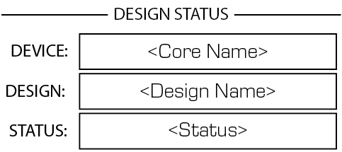
- Device – The name of the Core as defined in Q-SYS Designer.
- Design – The name of the currently running design.
- Status –
- OK – Audio is good, hardware is good.
- Compromised – Audio is good but a redundancy mechanism is active (one LAN down but the other is still up) or a non-fatal hardware problem exists (fans too slow, temperature higher than expected, etc.)
- Fault – Audio is not passing, or hardware is malfunctioning or mis-configured
- Missing – A piece of hardware, defined in the design, has not been discovered. Audio is not passing through that piece of hardware.
- Initializing – Starting the firmware, configuration update, and the design. Audio is obviously bad.
- Not Present – A virtual component in the design, that is designated as Dynamically Paired, and Not Required, has no hardware assigned to it.
System Status
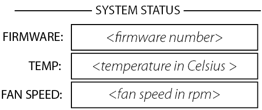
- Firmware – A three-section number identifying the major release, minor release, and maintenance release. For example, 5.0.06.
- Temp – The current chassis temperature of the Core.
- Compromised threshold = 60° C
- Fault threshold = 70° C
- Fan Speed – This number varies with the temperature.
LAN A
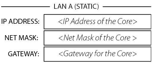
- Static or Auto – Displays next to LAN A, indicates if the Core's IP Address is Static or Automatic.
- IP Address – The IP Address assigned to the Core's LAN A. LAN A is the primary Q-LAN connection to the Core, and is required.
- Net Mask – The Net Mask assigned to the Core.
- Gateway – The Gateway assigned to the Core.
Note: You can edit this information in Core Manager.
LAN B
LAN B is used for redundancy, and is not required. The information is the same as LAN A.
Input / Flex In Channels Status
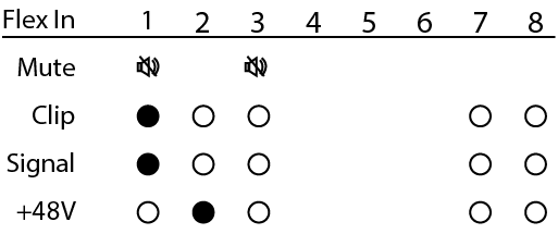
The Input and Flex Input screens show the Mute, Clip, Signal, and +48V (phantom power) for the eight Mic/Line input channels.
- Mute – Displays a "muted loudspeaker" when the channel is muted.
- Clip – Displays a solid circle under the channel having an input signal that is overdriving the associated channel input.
- Signal – Displays a solid circle when there is a signal present on the associated channel.
- +48V – Displays a solid circle when the phantom power is turned on for the associated channel.
Note: If the Flex channel is set to Output, there is no information for that channel on the Flex In screen.
Output / Flex Out Channels Status
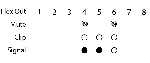
The Output and Flex Output screens show the Mute, Clip, and Signal, for the eight Mic/Line output channels.
- Mute – Displays a "muted loudspeaker" when the channel is muted.
- Clip – Displays a solid circle under the channel having an output signal over driving the associated channel output.
- Signal – Displays a solid circle when there is a signal present on the associated channel.
Note: If a Flex channel is set to Input, there is no information shown under the same channel on the Flex Out screen.
The POTS Controller component controls the features of the Q-SYS interface with a Plain Old Telephone Service (POTS).
If you are connecting to an analog phone system, you can connect from the wall RJ-11 jack directly to Q-SYS hardware supporting a POTS connection:
- The Core 110f and Core 110c provide a single RJ-11 telephone connection.
- The CTEL4 – Analog Telephony Card provides four RJ-11 telephone connections.
If you are connecting to a digital system, you can use an FXO Gateway that has an analog POTS connection and a network connection. For more information, visit the POTS Controller topic.
|
Technical Specifications |
|
|---|---|
| Input / Output Impedance |
600 ohms, nominal |
| Frequency Response |
300Hz - 3.3kHz +/- 0.5dB |
| Dynamic Range |
54 dB |
| Station Port Compatibility |
Two-wire ring start |
| Ringer Equivalence |
CTEL4: 0.0B Core 110f: 0.1 Core 11c: 0.1 |
| Electronic or 1A2 Line Key |
No1 |
| PABX Loop |
No1 |
| Trunk Port Compatibility |
Two-wire loop start |
| Number of phone lines |
CTEL4: 4 lines Core 110f: 1 line Core 110c: 1 line |
| Loop Current Interruption (CPC Pulse) |
Interpreted as line disconnect |
1. Each Q-SYS phone line is meant to be connected to a single PSTN line (FXO). It does not control a multi-line PBX or interface with an FXS.
